ac5uuw00002956
|
SHIFT CONTROL MODULE REMOVAL/INSTALLATION [C66M-R]
id0515m8160200
Removal
1. Shift the shift lever to the neutral position.
2. Remove the plug hole plate. (See PLUG HOLE PLATE REMOVAL/INSTALLATION [SKYACTIV-G 2.0, SKYACTIV-G 2.5].)
3. Disconnect the negative battery cable. (See NEGATIVE BATTERY CABLE DISCONNECTION/CONNECTION [SKYACTIV-G 2.0, SKYACTIV-G 2.5].) (See NEGATIVE BATTERY CABLE DISCONNECTION/CONNECTION [SKYACTIV-G 2.0, SKYACTIV-G 2.5 (WITHOUT i-stop)].)
4. Remove the air cleaner and air hose as a single unit. (See INTAKE-AIR SYSTEM REMOVAL/INSTALLATION [SKYACTIV-G 2.0, SKYACTIV-G 2.5].)
5. Remove the battery and battery tray. (See BATTERY REMOVAL/INSTALLATION [SKYACTIV-G 2.0, SKYACTIV-G 2.5].)
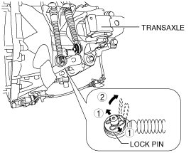
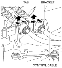
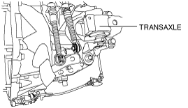
6. Disconnect the control cable from the transaxle.
ac5uuw00002956
|
ac5uuw00002957
|
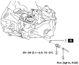
7. Remove the neutral switch in the order shown in the figure
ac5uuw00002958
|
|
1
|
Connector
|
|
2
|
Neutral switch
|
|
3
|
Gasket
|
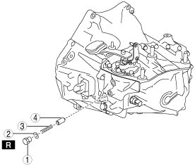
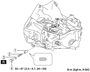
8. Remove the detent ball pin in the order shown in the figure
ac5uuw00002959
|
|
1
|
Plug
|
|
2
|
Gasket
|
|
3
|
Spring
|
|
4
|
Detent ball pin
|
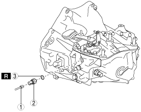
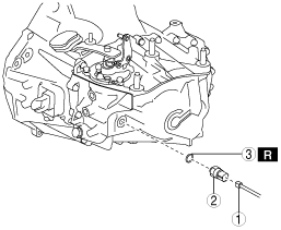
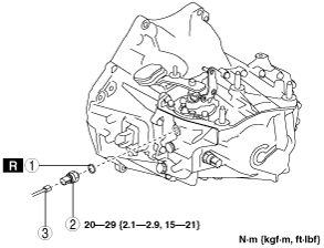
9. Remove the back-up light switch in the order shown in the figure
ac5uuw00002960
|
|
1
|
Connector
|
|
2
|
Back-up light switch
|
|
3
|
Gasket
|
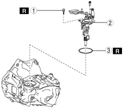
10. Remove the shift control module in the order shown in the figure
ac5uuw00002961
|
|
1
|
Breather
|
|
2
|
Shift control module
|
|
3
|
O-ring
|
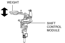
Installation
1. Verify that the shift control module is in the neutral position.
ac5uuw00002962
|
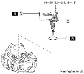
2. Install the shift control module in the order shown in the figure
ac5uuw00002963
|
|
1
|
O-ring
|
|
2
|
Shift control module
|
|
3
|
Breather
|
3. Install the back-up light switch in the order shown in the figure
ac5uuw00002964
|
|
1
|
Gasket
|
|
2
|
Back-up light switch
|
|
3
|
Connector
|
4. Install the detent ball pin in the order shown in the figure
ac5uuw00002965
|
|
1
|
Detent ball pin
|
|
2
|
Spring
|
|
3
|
Gasket
|
|
4
|
Plug
|
5. Install the neutral switch in the order shown in the figure
ac5uuw00002966
|
|
1
|
Gasket
|
|
2
|
Neutral switch
|
|
3
|
Connector
|
6. Connect the control cable to the transaxle.
ac5uuw00002967
|
7. Make sure that the shift lever can be shifted smoothly.
8. Install the battery tray and battery. (See BATTERY REMOVAL/INSTALLATION [SKYACTIV-G 2.0, SKYACTIV-G 2.5].)
9. Install the air cleaner and air hose as a single unit. (See INTAKE-AIR SYSTEM REMOVAL/INSTALLATION [SKYACTIV-G 2.0, SKYACTIV-G 2.5].)
10. Connect the negative battery cable. (See NEGATIVE BATTERY CABLE DISCONNECTION/CONNECTION [SKYACTIV-G 2.0, SKYACTIV-G 2.5].) (See NEGATIVE BATTERY CABLE DISCONNECTION/CONNECTION [SKYACTIV-G 2.0, SKYACTIV-G 2.5 (WITHOUT i-stop)].)
11. Install the plug hole plate. (See PLUG HOLE PLATE REMOVAL/INSTALLATION [SKYACTIV-G 2.0, SKYACTIV-G 2.5].)