TORQUE SENSOR
id061300245400
Purpose/ Function
• The torque sensor detects the steering torque and the steering direction, and outputs the signal to the Electric Power Steering (EPS) Control Module (CM).
Construction (Without Lane-Keep Assist System)
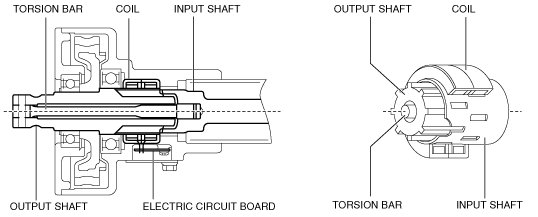
• The non-contact type torque sensor is installed to the top of the steering column and consists of the following parts.
-
― Torsion bar: Connects the input shaft and output shaft.
― Input shaft: When the steering torque is input, the magnetic field is changed.
― Output shaft: Torque from the EPS motor is transmitted to the intermediate shaft.
― Coil: Assembled onto each shaft, converts magnetic field of input shaft to an electric signal.
― Electric circuit board: Inputs the coil electric signal to the EPS CM.
Operation (Without Lane-Keep Assist System)
• When the steering wheel is operated, the torsion bar connecting the input and output shafts twists.
• From the twisting of the torsion bar, the input and output shafts move relative to each other.As a result, the positions of the input shaft window and output shaft projection change, and the electric field is changed.
• The coil converts the change in electric field to an electric signal and the electric circuit board outputs it to the EPS CM.
• The EPS CM calculates the electric signal from this torque sensor internally and uses it for various controls as a steering torque signal.
Construction (With Lane-Keep Assist System)
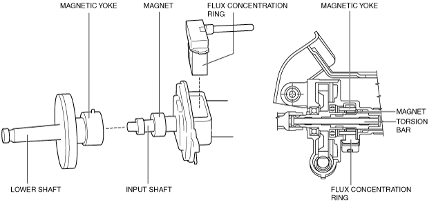
• The Hall IC-type torque sensor is installed to the top of the steering column and consists of the following parts.
-
― Magnet: Assembled in a ring shape to the input shaft, it generates magnetic flux.
― Magnetic yoke: Assembled to the lower shaft, it converts magnetic flux transmitted to the flux concentration ring according to the position of the tooth area and the magnet.
― Flux concentration ring: Equipped with two Hall ICs at the front edge, it reads the change in magnetic flux.
Operation (With Lane-Keep Assist System)
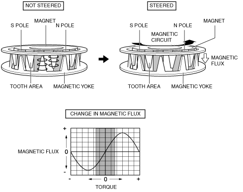
• When the steering wheel is centered (not steered), magnetic flux is not transmitted to the Hall ICs because the tooth area of the magnetic yoke shunts the magnetic flux of the magnet.
• Magnetic flux is transmitted to the Hall ICs when the steering wheel is operated because the positions of the magnet and the tooth area of the magnetic yoke change as the torsion bar connected to the input shaft and lower shaft twists.
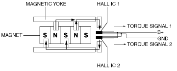
• The Hall ICs convert the change in magnetic flux to an electric signal and output it to the EPS CM.
• Electrical signals from each of the two Hall ICs in the torque sensor are calculated in the EPS CM and used for each type of control as steering torque signals.
• By the detection of two signals, the reliability of the steering torque calculated by the EPS CM and the malfunction detection performance of the torque sensor have been improved.
Fail-safe
|
DTC No.
|
Fail-safe function
|
|
C200B:02
|
• Control disabled
• Power steering malfunction indicator light: Illuminates
|
|
C200B:16
|
|
C200B:1C
|
• Control is maintained in the backup control
• Power steering malfunction indicator light: Illuminates
|
|
C200B:62
|
• Control disabled
• Power steering malfunction indicator light: Illuminates
|
|
C200B:64
|
|
C200B:85
|
|
C200C:1C
|
• Control is maintained in the backup control
• Power steering malfunction indicator light: Illuminates
|