STEERING COLUMN AND SHAFT
id061300245800
Purpose/Function
• The steering input force, generated when the driver operates the steering wheel, is transmitted to the steering gear.
Construction
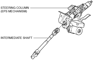
• The steering column and shaft consists of the steering column with a built-in Electric Power Steering (EPS) mechanism and the intermediate shaft.
• As a result of impact absorbing mechanisms on the steering column and intermediate shaft, when a collision occurs, the steering shaft effectively absorbs the impact energy that would be transmitted to the driver, thereby reducing injury.
• A steering column with tilt/telescoping mechanism has been adopted, allowing fine adjustment of the driving posture.
Operation
EPS mechanism
• Based on the steering torque signal from the torque sensor and the vehicle speed and engine speed signals from the PCM, the EPS Control Module (CM) drives the EPS motor and transmits the assist torque to the intermediate shaft via the deceleration mechanism.
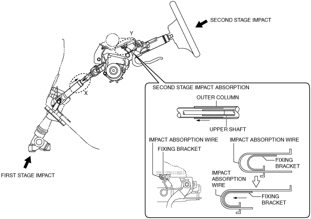
Energy absorbing system (Without Lane-Keep Assist System)
• At the moment of a collision, when impact energy (first stage impact) is input from the vehicle front due to the rearward collapse of the steering gear, the intermediate shaft contracts to absorb the impact from the driver. (Section X in the figure)
• When the body of the driver contacts the steering wheel (second stage impact), the fixing bracket comes off the dashboard member, and the upper shaft and the outer column slide forward. At this time, the impact absorption wire (one part secured to instrument panel member) deforms to absorb the impact to the driver. (Section Y in the figure)
Energy absorbing system (With Lane-Keep Assist System)
• At the moment of a collision, when impact energy (first stage impact) is input from the vehicle front due to the rearward collapse of the steering gear, the intermediate shaft contracts to absorb the impact from the driver. (Section X in the figure)
• When the body of the driver contacts the steering wheel (second stage impact), the fixing bracket comes off the dashboard member, and the upper shaft and the outer column slide forward. At this time, the impact absorption plate (one part secured to instrument panel member, another part to fixing bracket) deforms (area A shown in figure cracks) to absorb the impact to the driver. (Section Y in the figure)
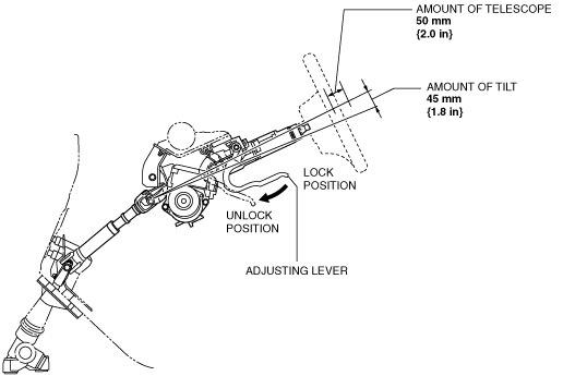
Tilt/telescope mechanism
• The steering wheel can be moved in the up/down and forward/backward direction when the adjusting lever is pressed towards the front of the vehicle to release the lock of the tilt/telescope system.
• The tilt/telescope mechanism has a movement range of
45 mm {1.8 in} (tilt)/
50 mm {2.0 in} (telescope) and can be adjusted, without steps, to anywhere in this range.
Fail-safe
• Function not equipped.