 |
ac5wzn00000837
ON-BOARD DIAGNOSTIC
id070200126600
Outline
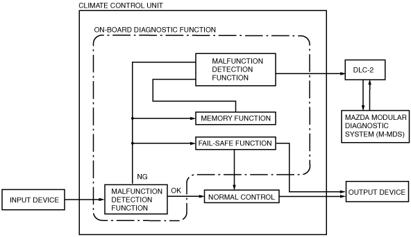
Block Diagram
ac5wzn00000837
|
Function
Malfunction detection function
Memory function
Malfunction indication function
Full-auto air conditioner
|
DTC |
Warning lamp |
Malfunction location |
Detected condition |
Fail safe |
Drive cycle |
Self test type*1 |
Memory function |
|---|---|---|---|---|---|---|---|
|
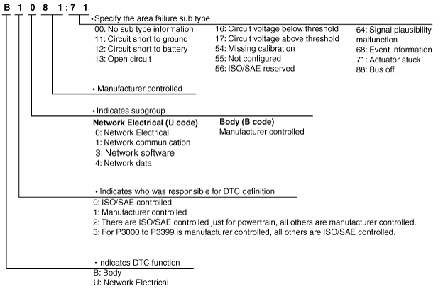
B1081:71
|
—
|
• Driver-side air mix actuator (L.H.D.)
• Passenger-side air mix actuator (R.H.D.)
|
Motor lock
|
X
|
—
|
C
|
X
|
|
B1082:71
|
—
|
• Passenger-side air mix actuator (L.H.D.)
• Driver-side air mix actuator (R.H.D.)
|
Motor lock
|
X
|
—
|
C
|
X
|
|
B1086:71
|
—
|
Airflow mode actuator
|
Motor lock
|
X
|
—
|
C
|
X
|
|
B1A61:11
|
—
|
Cabin temperature sensor
|
Circuit short to ground
|
X
|
—
|
C, D
|
X
|
|
B1A61:13
|
—
|
Circuit open
|
X
|
—
|
C, D
|
X
|
|
|
B1A63:12
|
—
|
Solar radiation sensor (RH)
|
Circuit shot to power supply
|
—
|
—
|
C, D
|
X
|
|
B1A63:13
|
—
|
Circuit open
|
—
|
—
|
D
|
X
|
|
|
B1A64:12
|
—
|
Solar radiation sensor (LH)
|
Circuit shot to power supply
|
—
|
—
|
C, D
|
X
|
|
B1A64:13
|
—
|
Circuit open
|
—
|
—
|
D
|
X
|
|
|
B1B71:11
|
—
|
Evaporator temperature sensor
|
Circuit short to ground
|
X
|
—
|
C, D
|
X
|
|
B1B71:13
|
—
|
Circuit open
|
X
|
—
|
C, D
|
X
|
|
|
B1C1A:11
|
—
|
• Driver-side air mix actuator (potentiometer) (L.H.D.)
• Passenger-side air mix actuator (potentiometer) (R.H.D.)
|
Circuit short to ground
|
X
|
—
|
C, D
|
X
|
|
B1C1A:13
|
—
|
Circuit open
|
X
|
—
|
C, D
|
X
|
|
|
B1C1B:11
|
—
|
• Passenger-side air mix actuator (potentiometer) (L.H.D.)
• Driver-side air mix actuator (potentiometer) (R.H.D.)
|
Circuit short to ground
|
X
|
—
|
C, D
|
X
|
|
B1C1B:13
|
—
|
Circuit open
|
X
|
—
|
C, D
|
X
|
|
|
B1C1C:11
|
—
|
Airflow mode actuator (potentiometer)
|
Circuit short to ground
|
X
|
—
|
C, D
|
X
|
|
B1C1C:13
|
—
|
Circuit open
|
X
|
—
|
C, D
|
X
|
|
|
U0010:88
|
—
|
CAN communication system
|
Bus off
|
X
|
—
|
C
|
X
|
|
U0155:00
|
—
|
Lost communication with instrument cluster
|
No sub type information
|
X
|
—
|
C, D
|
X
|
|
U0423:68
|
—
|
Invalid date received from Instrument cluster
|
Event information
|
X
|
—
|
C, D
|
X
|
|
U200D:11
|
—
|
Climate control unit circuit voltage (+5V)
|
Circuit short to ground
|
—
|
—
|
C, D
|
X
|
|
U2300:54
|
—
|
Configuration error
|
Data not received
|
—
|
—
|
C, D
|
X
|
|
U2300:55
|
—
|
Not configured
|
—
|
—
|
C, D
|
—
|
|
|
U2300:56
|
—
|
Ineffective/non-interchangeable data read
|
—
|
—
|
C, D
|
X
|
|
|
U2300:64
|
—
|
Error value read
|
—
|
—
|
C, D
|
X
|
|
|
U3003:16
|
—
|
Climate control unit power supply voltage (B+, IG1)
|
Power supply voltage decreases (9.98 V or less)
|
—
|
—
|
C, D
|
X
|
|
U3003:17
|
—
|
Climate control unit power supply voltage (B+, IG1)
|
Power supply voltage increases (16.21 V or more (B+, IG1))
|
—
|
—
|
C, D
|
X
|
|
U300E:13
|
—
|
Climate control unit power supply circuit (IG1)
|
Circuit open
|
—
|
—
|
C, D
|
X
|
Manual air conditioner
|
DTC |
Warning lamp |
Malfunction location |
Detected condition |
Fail safe |
Drive cycle |
Self test type*1 |
Memory function |
|---|---|---|---|---|---|---|---|
|
B1086:71
|
—
|
Airflow mode actuator
|
Motor lock
|
X
|
—
|
C
|
X
|
|
B13AA:71
|
—
|
Air mix actuator
|
Motor lock
|
X
|
—
|
C
|
X
|
|
B13AB:12
|
—
|
Air mix actuator (potentiometer)
|
Circuit short to power supply
|
X
|
—
|
C, D
|
X
|
|
B13AB:13
|
—
|
Circuit open
|
X
|
—
|
C, D
|
X
|
|
|
B1B71:11
|
—
|
Evaporator temperature sensor
|
Circuit short to ground
|
X
|
—
|
C, D
|
X
|
|
B1B71:13
|
—
|
Circuit open
|
X
|
—
|
C, D
|
X
|
|
|
B1C1C:12
|
—
|
Airflow mode actuator (potentiometer)
|
Circuit short to power supply
|
X
|
—
|
C, D
|
X
|
|
B1C1C:13
|
—
|
Circuit open
|
X
|
—
|
C, D
|
X
|
|
|
U0010:88
|
—
|
CAN communication system
|
Bus off
|
X
|
—
|
C
|
X
|
|
U0155:00
|
—
|
Lost communication with instrument cluster
|
No sub type information
|
X
|
—
|
C, D
|
X
|
|
U0423:68
|
—
|
Invalid date received from Instrument cluster
|
Event information
|
X
|
—
|
C, D
|
X
|
|
U200D:11
|
—
|
Climate control unit circuit voltage (+5V)
|
Circuit short to ground
|
—
|
—
|
C, D
|
X
|
|
U2300:54
|
—
|
Configuration error
|
Data not received
|
—
|
—
|
C, D
|
X
|
|
U2300:55
|
—
|
Not configured
|
—
|
—
|
C, D
|
—
|
|
|
U2300:56
|
—
|
Ineffective/non-interchangeable data read
|
—
|
—
|
C, D
|
X
|
|
|
U2300:64
|
—
|
Error value read
|
—
|
—
|
C, D
|
X
|
|
|
U3003:16
|
—
|
Climate control unit power supply voltage (B+, IG1)
|
Power supply voltage decreases (9.98 V or less)
|
—
|
—
|
C, D
|
X
|
|
U3003:17
|
—
|
Climate control unit power supply voltage (B+, IG1)
|
Power supply voltage increases (16.21 V or more (B+, IG1))
|
—
|
—
|
C, D
|
X
|
|
U300E:13
|
—
|
Climate control unit power supply circuit (IG2)
|
Circuit open
|
—
|
—
|
C, D
|
X
|
ac5wzn00001320
|
ac5wzn00001326
|
PID/data monitor
PID/data monitor table
Full-auto air conditioner
|
PID name (definition) |
Unit/Condition |
Operation Status (Reference) |
Input part |
|---|---|---|---|
|
A/C_SW
|
Off/On
|
• A/C switch OFF: Off
• A/C switch ON: On
|
Climate control unit
|
|
AUTO_SW
|
Off/On
|
• AUTO switch OFF: Off
• AUTO switch ON: On
|
Climate control unit
|
|
B_MT_RLY_CS
|
Off/On
|
• Blower relay off: Off
• Blower relay on: On
|
Climate control unit
|
|
DEF_SW
|
Off/On
|
• DEFROSTER switch OFF: Off
• DEFROSTER switch ON: On
|
Climate control unit
|
|
DUAL_SW
|
Off/On
|
• DUAL switch OFF: Off
• DUAL switch ON: On
|
Climate control unit
|
|
ELE_W/P
|
Off/On
|
• Water pump off: Off
• Water pump on: On
|
Water pump
|
|
ENG_C_TMP
|
°C, °F
|
Engine coolant temperature is displayed
|
Engine coolant temperature sensor
|
|
EVA_TMP_SEN
|
°C, °F
|
Evaporator temperature is displayed
|
Evaporator temperature sensor
|
|
F_REC_CS
|
Off/On
|
• Forced recirculate control off: Off
• Forced recirculate control on: On
|
Climate control unit
|
|
FRE_SW
|
Off/On
|
• FRESH switch OFF: Off
• FRESH switch ON: On
|
Climate control unit
|
|
HC_TMP_SEN
|
°C, °F
|
Heater core temperature is displayed
|
Heater core temperature sensor
|
|
INC_TMP_SEN
|
°C, °F
|
Cabin temperature is displayed
|
Cabin temperature sensor
|
|
M_DOWN_SW
|
Off/On
|
• MODE switch (DOWN) OFF: Off
• MODE switch (DOWN) ON: On
|
Climate control unit
|
|
M_UP_SW
|
Off/On
|
• MODE switch (UP) OFF: Off
• MODE switch (UP) ON: On
|
Climate control unit
|
|
OFF_SW
|
Off/On
|
• OFF switch OFF: Off
• OFF switch ON: On
|
Climate control unit
|
|
OUT_CAR_TMP
|
°C, °F
|
Ambient temperature is displayed
|
Ambient temperature sensor
|
|
R/DEF_CS
|
Off/On
|
• Rear defroster off: Off
• Rear defroster on: On
|
Climate control unit
|
|
R/DEF_SW
|
Off/On
|
• Rear window defroster switch OFF: Off
• Rear window defroster switch ON: On
|
Climate control unit
|
|
REC_SW
|
Off/On
|
• RECIRCULATE switch OFF: Off
• RECIRCULATE switch ON: On
|
Climate control unit
|
|
S_HT_CUT_CS
|
No_Request/Cut
|
• Seat warmer signal cut control off: No_Request
• Seat warmer signal cut control on: Cut
|
Climate control unit
|
|
SLR_R_SEN_L
|
W/m2
|
Solar radiation amount is displayed
|
Solar radiation sensor
|
|
SLR_R_SEN_R
|
|||
|
STOP_ST
|
Available/
Not Available/
Error
|
• i-stop permit condition: Available
• i-stop inhibit condition: Not Available
• i-stop signal failure: Error
|
• Climate control unit
• PCM
|
|
UNIT_TMP
|
deg_C/deg_F
|
• Centigrade: deg_C
• Fahrenheit: deg_F
|
Climate control unit
|
Manual air conditioner
|
PID name (definition) |
Unit/Condition |
Operation Status (Reference) |
Input part |
|---|---|---|---|
|
A/C_SW
|
Off/On
|
• A/C switch OFF: Off
• A/C switch ON: On
|
Climate control unit
|
|
AUTO_SW
|
|
||
|
B_MT_RLY_CS
|
Off/On
|
• Blower relay off: Off
• Blower relay on: On
|
Climate control unit
|
|
DUAL_SW
|
|
||
|
ELE_W/P
|
|
||
|
ENG_C_TMP
|
°C, °F
|
Engine coolant temperature is displayed
|
Engine coolant temperature sensor
|
|
EVA_TMP_SEN
|
°C, °F
|
Evaporator temperature is displayed
|
Evaporator temperature sensor
|
|
FRE_SW
|
Off/On
|
• FRESH switch OFF: Off
• FRESH switch ON: On
|
Climate control unit
|
|
INC_TEMP_SEN
|
|
||
|
OFF_SW
|
Off/On
|
• OFF switch OFF: Off
• OFF switch ON: On
|
Climate control unit
|
|
OUT_CAR_TMP
|
°C, °F
|
Ambient temperature is displayed
|
Ambient temperature sensor
|
|
R/DEF_CS
|
Off/On
|
• Rear defroster off: Off
• Rear defroster on: On
|
Climate control unit
|
|
R/DEF_SW
|
Off/On
|
• Rear window defroster switch OFF: Off
• Rear window defroster switch ON: On
|
Climate control unit
|
|
REC_SW
|
Off/On
|
• RECIRCULATE switch OFF: Off
• RECIRCULATE switch ON: On
|
Climate control unit
|
|
STOP_ST
|
Available/
Not Available/
Error
|
• i-stop permit condition: Available
• i-stop inhibit condition: Not Available
• i-stop signal failure: Error
|
• Climate control unit
• PCM
|
A/C operation check mode
|
Mazda Modular Diagnostic System (M-MDS) display |
Target part |
Reference |
|---|---|---|
|
Air Mix Actuator
|
• Air mix actuator
• Air mix door
|
(See A/C operation check mode)
|
|
Air conditioning compressor
|
• A/C compressor
|
|
|
Air Intake Actuator
|
• Air intake actuator
• Air intake door
|
|
|
Blower Motor Speed
|
• Blower motor
|
|
|
Air Flow Mode Actuator
|
• Airflow mode actuator
• Airflow mode door
|
|
|
Illumination of All Indicator Lights
|
• Climate control unit
|
Air mix actuator (Full-auto air conditioner)
Operation
|
Step |
Air mix actuator |
Airflow mode actuator |
Blower speed |
Magnet clutch |
Air intake actuator |
|---|---|---|---|---|---|
|
1
|
0 %
|
VENT
|
3rd
|
ON
|
FRESH
|
|
2
|
50 %
|
||||
|
3
|
100 %
|
||||
|
4
|
50 %
|
Display
|
Step |
Temperature (°C {°F}) |
Airflow mode |
Blower volume |
A/C |
Recirculate switch indicator light |
Fresh switch indicator light |
|---|---|---|---|---|---|---|
|
1
|
20.0 {68}
|
 |
 |
Displayed
|
Not illuminated
|
Illuminated
|
|
2
|
20.5 {68.9}
|
|||||
|
3
|
21.0 {70}
|
|||||
|
4
|
20.5 {68.9}
|
Air mix actuator (Manual air conditioner)
Operation
|
Step |
Air mix actuator |
Airflow mode actuator |
Blower speed |
Magnet clutch |
Air intake actuator |
|---|---|---|---|---|---|
|
1
|
0 %
|
VENT
|
5th
|
ON
|
FRESH
|
|
2
|
100 %
|
Display
|
Step |
A/C switch indicator light |
Recirculate switch indicator light |
Rear window defogger switch indicator light |
|---|---|---|---|
|
1
|
Illuminated
|
Not illuminated
|
Not illuminated
|
|
2
|
A/C compressor (Full-auto air conditioner)
Operation
|
Step |
Air mix actuator |
Airflow mode actuator |
Blower speed |
Magnet clutch |
Air intake actuator |
|---|---|---|---|---|---|
|
1
|
0 %
|
VENT
|
5th
|
ON
|
FRESH
|
|
2
|
OFF
|
Display
|
Step |
Temperature (°C {°F}) |
Airflow mode |
Blower volume |
A/C |
Recirculate switch indicator light |
Fresh switch indicator light |
|---|---|---|---|---|---|---|
|
1
|
8 {46}
|
|
 |
Displayed
|
Not illuminated
|
Illuminated
|
|
2
|
Not displayed
|
A/C compressor (Manual air conditioner)
Operation
|
Step |
Air mix actuator |
Airflow mode actuator |
Blower speed |
Magnet clutch |
Air intake actuator |
|---|---|---|---|---|---|
|
1
|
0 %
|
VENT
|
5th
|
ON
|
FRESH
|
|
2
|
OFF
|
Display
|
Step |
A/C switch indicator light |
Recirculate switch indicator light |
Rear window defogger switch indicator light |
|---|---|---|---|
|
1
|
Illuminated
|
Not illuminated
|
Illuminated
|
|
2
|
Not illuminated
|
Air intake actuator (Full-auto air conditioner)
Operation
|
Step |
Air mix actuator |
Airflow mode actuator |
Blower speed |
Magnet clutch |
Air intake actuator |
|---|---|---|---|---|---|
|
1
|
0 %
|
VENT
|
3rd
|
ON
|
FRESH
|
|
2
|
RECIRCULATE
|
||||
|
3
|
OFF
|
FRESH
|
|||
|
4
|
RECIRCULATE
|
Display
|
Step |
Temperature (°C {°F}) |
Airflow mode |
Blower volume |
A/C |
Recirculate switch indicator light |
Fresh switch indicator light |
|---|---|---|---|---|---|---|
|
1
|
4 {39}
|
|
|
Displayed
|
Not illuminated
|
Illuminated
|
|
2
|
Illuminated
|
Not illuminated
|
||||
|
3
|
Not displayed
|
Not illuminated
|
Illuminated
|
|||
|
4
|
Illuminated
|
Not illuminated
|
Air intake actuator (Manual air conditioner)
Operation
|
Step |
Air mix actuator |
Airflow mode actuator |
Blower speed |
Magnet clutch |
Air intake actuator |
|---|---|---|---|---|---|
|
1
|
0 %
|
VENT
|
5th
|
ON
|
FRESH
|
|
2
|
RECIRCULATE
|
||||
|
3
|
OFF
|
FRESH
|
|||
|
4
|
RECIRCULATE
|
Display
|
Step |
A/C switch indicator light |
Recirculate switch indicator light |
Rear window defogger switch indicator light |
|---|---|---|---|
|
1
|
Illuminated
|
Not illuminated
|
Not illuminated
|
|
2
|
Illuminated
|
||
|
3
|
Not illuminated
|
Not illuminated
|
|
|
4
|
Illuminated
|
Blower motor (Full-auto air conditioner)
Operation
|
Step |
Air mix actuator |
Airflow mode actuator |
Blower speed |
Magnet clutch |
Air intake actuator |
|---|---|---|---|---|---|
|
1
|
50 %
|
VENT
|
OFF
|
OFF
|
FRESH
|
|
2
|
1st
|
ON
|
|||
|
3
|
3rd
|
||||
|
4
|
5th
|
||||
|
5
|
7th
|
Display
|
Step |
Temperature (°C {°F}) |
Airflow mode |
Blower volume |
A/C |
Recirculate switch indicator light |
Fresh switch indicator light |
|---|---|---|---|---|---|---|
|
1
|
1 {34}
|
|
Not displayed
|
Not displayed
|
Not illuminated
|
Illuminated
|
|
2
|
 |
Displayed
|
||||
|
3
|
|
|||||
|
4
|
|
|||||
|
5
|
 |
Blower motor (Manual air conditioner)
Operation
|
Step |
Air mix actuator |
Airflow mode actuator |
Blower speed |
Magnet clutch |
Air intake actuator |
|---|---|---|---|---|---|
|
1
|
50 %
|
VENT
|
OFF
|
OFF
|
FRESH
|
|
2
|
1st
|
ON
|
|||
|
3
|
3rd
|
||||
|
4
|
5th
|
||||
|
5
|
7th
|
Display
|
Step |
A/C switch indicator light |
Recirculate switch indicator light |
Rear window defogger switch indicator light |
|---|---|---|---|
|
1
|
Not illuminated
|
Not illuminated
|
Not illuminated
|
|
2
|
Illuminated
|
||
|
3
|
|||
|
4
|
|||
|
5
|
Airflow mode actuator (Full-auto air conditioner)
Operation
|
Step |
Air mix actuator |
Airflow mode actuator |
Blower speed |
Magnet clutch |
Air intake actuator |
|---|---|---|---|---|---|
|
1
|
50 %
|
VENT
|
5th
|
ON
|
FRESH
|
|
2
|
BI-LEVEL
|
||||
|
3
|
HEAT
|
||||
|
4
|
DEF/HEAT
|
||||
|
5
|
DEFROSTER
|
Display
|
Step |
Temperature (°C {°F}) |
Airflow mode |
Blower volume |
A/C |
Recirculate switch indicator light |
Fresh switch indicator light |
|---|---|---|---|---|---|---|
|
1
|
3 {37}
|
|
|
Displayed
|
Not illuminated
|
Illuminated
|
|
2
|
 |
|||||
|
3
|
 |
|||||
|
4
|
 |
|||||
|
5
|
 |
Airflow mode actuator (Manual air conditioner)
Operation
|
Step |
Air mix actuator |
Airflow mode actuator |
Blower speed |
Magnet clutch |
Air intake actuator |
|---|---|---|---|---|---|
|
1
|
50 %
|
VENT
|
5th
|
ON
|
FRESH
|
|
2
|
BI-LEVEL
|
||||
|
3
|
HEAT
|
||||
|
4
|
DEF/HEAT
|
||||
|
5
|
DEFROSTER
|
Display
|
Step |
A/C switch indicator light |
Recirculate switch indicator light |
Rear window defogger switch indicator light |
|---|---|---|---|
|
1
|
Illuminated
|
Not illuminated
|
Not illuminated
|
|
2
|
|||
|
3
|
|||
|
4
|
|||
|
5
|
Indicator light (Full-auto air conditioner)
Operation
|
Step |
Air mix actuator |
Airflow mode actuator |
Blower speed |
Magnet clutch |
Air intake actuator |
|---|---|---|---|---|---|
|
—
|
50 %
|
VENT
|
OFF
|
OFF
|
FRESH
|
Display
|
Step |
Temperature (°C {°F}) |
Airflow mode |
Blower volume |
A/C |
Recirculate switch indicator light |
Fresh switch indicator light |
|---|---|---|---|---|---|---|
|
—
|
All indicator displayed
|
Illuminated
|
Illuminated
|
|||
Indicator light (Manual air conditioner)
Operation
|
Step |
Air mix actuator |
Airflow mode actuator |
Blower speed |
Magnet clutch |
Air intake actuator |
|---|---|---|---|---|---|
|
—
|
50 %
|
VENT
|
OFF
|
OFF
|
FRESH
|
Display
|
Step |
A/C switch indicator light |
Recirculate switch indicator light |
Rear window defogger switch indicator light |
|||
|---|---|---|---|---|---|---|
|
—
|
Illuminated
|
Illuminated
|
Illuminated
|
|||
A/C operation check stop (Full-auto air conditioner)
Operation
|
Step |
Air mix actuator |
Airflow mode actuator |
Blower speed |
Magnet clutch |
Air intake actuator |
|---|---|---|---|---|---|
|
—
|
50 %
|
VENT
|
OFF
|
OFF
|
FRESH
|
Display
|
Step |
Temperature (°C {°F}) |
Airflow mode |
Blower volume |
A/C |
Recirculate switch indicator light |
Fresh switch indicator light |
|---|---|---|---|---|---|---|
|
—
|
0 {32}
|
|
Not displayed
|
Not displayed
|
Not illuminated
|
Illuminated
|
A/C operation check stop (Manual air conditioner)
Operation
|
Step |
Air mix actuator |
Airflow mode actuator |
Blower speed |
Magnet clutch |
Air intake actuator |
|---|---|---|---|---|---|
|
—
|
50 %
|
VENT
|
OFF
|
OFF
|
FRESH
|
Display
|
Step |
A/C switch indicator light |
Recirculate switch indicator light |
Rear window defogger switch indicator light |
|---|---|---|---|
|
—
|
Not illuminated
|
Not illuminated
|
Not illuminated
|