AIRFLOW VOLUME CONTROL [FULL-AUTO AIR CONDITIONER]
id0740a1310400
Purpose
• The airflow volume control changes the airflow volume according to the vehicle environment.
Function
• The airflow volume control changes the operation of the blower motor according to the operations of the airflow volume control switch or temperature control dial and the vehicle environment to change the airflow volume.
• The airflow volume control has automatic and manual controls.
• The airflow volume automatic control performs the following correction:
-
― Engine coolant temperature correction (warm-up correction)
― Mild start correction
― MAX HOT and MAX COLD correction
― Start-up window fogging prevention correction
― Starting compensation correction
― Defroster correction
― Start-up burn-out prevention function
Airflow Volume Automatic Control
-
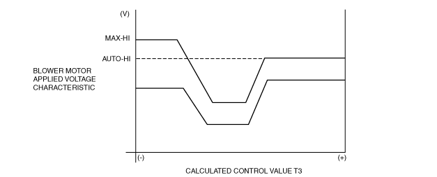
• The climate control unit calculates the blower motor applied voltage characteristic based on the set temperature, ambient temperature, and solar radiation amount.
• The climate control unit compares the blower motor applied voltage characteristic with the target temperature (calculated control value T3) and then determines the blower motor applied voltage (AUTO voltage).
• Calculated control value T3 is the target cabin temperature as set by the climate control unit based on differences between the set temperatures and temperatures input from the sensors.
• Calculated control value T3 is constantly calculated according to the changes in the set temperature and the signals input from the sensors.
Airflow Volume Manual Control
-
• The climate control unit changes the blower motor applied voltage (airflow volume) in seven steps according to the operation of the airflow volume control switch.
|
Airflow volume control switch
|
Blower motor applied voltage
|
|
1st
|
3.5 V
|
|
2nd
|
5.2 V
|
|
3rd
|
6.9 V
|
|
4th
|
8.6 V
|
|
5th
|
10.0 V
|
|
6th
|
12.1 V
|
|
7th
|
14.6 V*1, 13.0V*2
|
*1 :When the airflow mode is except HEAT.
*2 :When the airflow mode is HEAT.
Correction
-
Engine coolant temperature correction (warm-up correction)
-
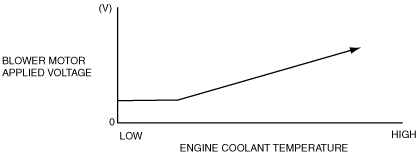
• The engine coolant temperature correction (warm-up correction) prevents high volume of cold air from coming out of the air vents after engine start in winter.
• The engine coolant temperature correction (warm-up correction) controls the blower motor applied voltage according to the increase in the engine coolant temperature.
• The engine coolant temperature correction is not performed during defroster correction, or when the cabin temperature is
20 °C {68 °F} or more and the airflow mode is in VENT mode.
-
Mild start correction
-
• The mild start correction prevents a high volume of warm air from coming out of the air vents when the blower motor is started in summer.
• The mild start correction limits the blower motor applied voltage for 3 s after the blower motor is started.
• The mild start correction is not performed when the cabin temperature is
20 °C {68 °F} or less or the airflow is in any mode other than VENT.
-
MAX HOT and MAX COLD correction
-
• The MAX HOT and MAX COLD correction fixes the blower motor applied voltage as indicated in the table when the temperature is set to MAX HOT or MAX COLD.
• The MAX HOT correction is not performed during engine coolant temperature correction.
European (L.H.D. U.K.) specs.
|
Correction name
|
Set temperature
|
Blower motor applied voltage
|
|
MAX HOT correction
|
29.0/84
|
12.1 (V): AUTO-HI
|
|
MAX COLD correction
|
15.0/60
|
14.6 (V): MAX-HI
|
Except European (L.H.D. U.K.) specs.
|
Correction name
|
Set temperature
|
Blower motor applied voltage
|
|
MAX HOT correction
|
32.0/90
|
12.1 (V): AUTO-HI
|
|
MAX COLD correction
|
18.0/64
|
14.6 (V): MAX-HI
|
-
Start-up window fogging prevention correction
-
• The start-up window fogging prevention correction prevents the windows from easily fogging when the following conditions are all met.
-
― Right after engine start
― Heater is operated
― Air is blowing from vents for defrosting
• The start-up window fogging prevention correction fixes the blower motor applied voltage at 0 V for 6 s after the ignition is switched ON.
• The start-up window fogging prevention correction is not performed when the airflow mode is in any mode other than HEAT, DEF/HEAT and defroster.
-
Starting compensation correction
-
• When the blower motor is started-up from the stopped status at the lowest speed (3.2 V), the starting compensation correction fixes the blower motor applied voltage at 4.4 V for 2 s to stabilize blower motor start-up operation.
-
Defroster correction
-
• When the defroster switch is turned on, the defroster correction adds a correction (+2 V) to the blower motor applied voltage to increase airflow volume.
-
Start-up burn-out prevention function
-
• The start-up burn-out prevention function prevents the blower motor from being burnt out because of excess current.
• When the blower motor is started-up from the stopped status with a blower motor applied voltage of 4.4 V or more, the blower motor applied voltage is fixed at 4.4 V for 1 s.
Construction
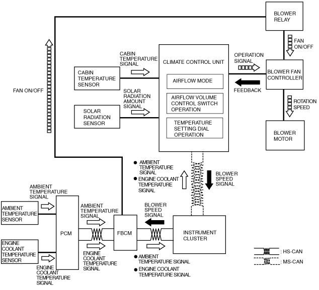
• The airflow volume control consists of the parts indicated in the following table:
|
Input device
|
Control part
|
Output device
|
|
• Airflow volume control switch (climate control unit)
• Temperature setting dial (climate control unit)
• Cabin temperature sensor
• Solar radiation sensor
• Ambient temperature sensor
• Engine coolant temperature sensor
• Airflow mode actuator
|
• Climate control unit
• PCM
• Front body control module (FBCM)
• Instrument cluster
|
• Blower fan controller
• Blower motor
|
Operation
1. When the ignition is switched ON (engine off or on), the front body control module (FBCM) turns the blower relay on.
2. When the airflow volume control switch on the climate control unit is turned on, the blower motor rotates.
3. The climate control determines the airflow volume based on the operations of the airflow volume control switch and the temperature setting dial, airflow mode condition, and signals from each sensor.
4. Based on the result of the airflow volume determination and correction, the climate control unit control the blower fan controller and changes the airflow volume (blower motor applied voltage).
5. The rotation speed of the blower motor changes according to the applied voltage from the blower fan controller.