|
1
|
INSPECT SELECTOR LEVER COMPONENT CONNECTOR
• Switch the ignition to off.
• Disconnect the negative battery cable.
• Disconnect the selector lever component connector.
• Inspect the connector engagement and connection condition and inspect the terminals for damage, deformation, corrosion, or disconnection.
• Is the connector normal?
|
Yes
|
Go to the next step.
|
|
No
|
Repair or replace the connector, then go to Step 7.
|
|
2
|
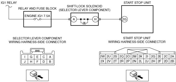
INSPECT FOR OPEN CIRCUIT OR SHORT TO GROUND IN SHIFT-LOCK SOLENOID POWER SUPPLY CIRCUIT
• Verify that the selector lever component connector is disconnected.
• Reconnect the negative battery cable.
• Switch the ignition ON (engine off or on).
• Measure the voltage at the selector lever component terminal A (wiring harness-side).
• Is the voltage B+?
|
Yes
|
Go to the next step.
|
|
No
|
Inspect the ENGINE.IG1 7.5 A fuse.
• If the fuse is burnt out:
-
― Refer to the wiring diagram and verify whether or not there is a common connector between ENGINE.IG1 7.5 A fuse and selector lever component terminal A.
If there is a common connector:
-
• Determine the malfunctioning part by inspecting the common connector and the terminal for corrosion, damage, or pin disconnection, and the common wiring harness for a short to ground.
• Repair or replace the malfunctioning part.
If there is no common connector:
-
• Repair or replace the wiring harness which has a short to ground.
• Replace the fuse.
• If the fuse is damaged:
-
― Replace the fuse.
• If the fuse is normal:
-
― Refer to the wiring diagram and verify whether or not there is a common connector between IG1 relay and selector lever component terminal A.
If there is a common connector:
-
• Determine the malfunctioning part by inspecting the common connector and the terminal for corrosion, damage, or pin disconnection, and the common wiring harness for an open circuit.
• Repair or replace the malfunctioning part.
If there is no common connector:
-
• Repair or replace the wiring harness which has an open circuit.
Go to Step 7.
|
|
3
|
INSPECT START STOP UNIT CONNECTOR
• Switch the ignition to off.
• Disconnect the negative battery cable.
• Disconnect the start stop unit connector.
• Inspect the connector engagement and connection condition and inspect the terminals for damage, deformation, corrosion, or disconnection.
• Is the connector normal?
|
Yes
|
Go to the next step.
|
|
No
|
Repair or replace the connector, then go to Step 7.
|
|
4
|
INSPECT FOR SHORT TO GROUND IN SHIFT-LOCK SOLENOID CIRCUIT
• Verify that the selector lever component and start stop unit connectors are disconnected.
• Inspect for continuity between selector lever component terminal H (wiring harness-side) and body ground.
• Is there continuity?
|
Yes
|
Refer to the wiring diagram and verify whether or not there is a common connector between selector lever component terminal H and start stop unit terminal 2G.
If there is a common connector:
• Determine the malfunctioning part by inspecting the common connector and the terminal for corrosion, damage, or pin disconnection, and the common wiring harness for a short to ground.
• Repair or replace the malfunctioning part.
If there is no common connector:
• Repair or replace the wiring harness which has a short to ground.
Go to Step 7.
|
|
No
|
Go to the next step.
|
|
5
|
INSPECT FOR OPEN CIRCUIT IN SHIFT-LOCK SOLENOID CIRCUIT
• Verify that the selector lever component and start stop unit connectors are disconnected.
• Inspect for continuity between selector lever component terminal H (wiring harness-side) and start stop unit terminal 2G (wiring harness-side).
• Is there continuity?
|
Yes
|
Go to the next step.
|
|
No
|
Refer to the wiring diagram and verify whether or not there is a common connector between selector lever component terminal H and start stop unit terminal 2G.
If there is a common connector:
• Determine the malfunctioning part by inspecting the common connector and the terminal for corrosion, damage, or pin disconnection, and the common wiring harness for an open circuit.
• Repair or replace the malfunctioning part.
If there is no common connector:
• Repair or replace the wiring harness which has an open circuit.
Go to Step 7.
|
|
6
|
INSPECT SHIFT-LOCK SOLENOID
• Inspect the shift-lock solenoid.
• Is the shift-lock solenoid normal?
|
Yes
|
Go to the next step.
|
|
No
|
Replace the selector lever component, then go to the next step.
|
|
7
|
VERIFY THAT REPAIRS HAVE BEEN COMPLETED
• Make sure to reconnect all disconnected connectors.
• Reconnect the negative battery cable.
• Clear the DTC for the start stop unit using the M-MDS.
• Switch the ignition ON (engine off or on) and wait for 30 min or more.
• Retrieve the start stop unit DTCs using the M-MDS.
• Is the same DTC displayed?
|
Yes
|
Repeat the inspection from Step 1.
• If the malfunction recurs, replace the start stop unit.
Go to the next step.
|
|
No
|
Go to the next step.
|
|
8
|
VERIFY IF OTHER DTCs DISPLAYED
• Are any other DTCs displayed?
|
Yes
|
Repair or replace the malfunctioning part according to the applicable DTC troubleshooting.
|
|
No
|
DTC troubleshooting completed.
|