 |
am6zzw00013623
PARKING SENSOR SYSTEM DOES NOT OPERATE [PARKING SENSOR SYSTEM]
id0903n7200300
Description
Possible Causes
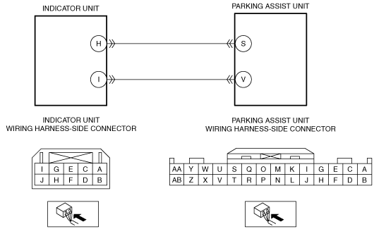
System Wiring Diagram
am6zzw00013623
|
Diagnostic Procedure
|
Step |
Inspection |
Action |
|
|---|---|---|---|
|
1
|
VERIFY ALL SYSTEM DTCs
• Switch the ignition off.
• Switch the ignition ON (engine off or on) and wait for 10 s or more.
• Perform a CMDTC self-test using the M-MDS.
• Are any DTCs displayed?
|
Yes
|
Repair or replace the malfunctioning part according to the applicable DTC troubleshooting.
|
|
No
|
Go to the next step.
|
||
|
2
|
VERIFY MALFUNCTION SYMPTOM
• Switch the ignition ON (engine off or on).
• Turn the parking sensor switch on.
• Does the parking sensor indicator turn on and is the buzzer activated?
|
Yes
|
If buzzer is activated after turning the indicator on:
• System is normal.
If buzzer is not activated:
• Perform an inspection referring to "PARKING SENSOR BUZZER DOES NOT ACTIVATE/BUZZER SOUND IS SMALL".
If indicator does not turn on:
• Perform an inspection referring to "PARKING SENSOR INDICATOR DOES NOT TURN ON".
|
|
No
|
Go to the next step.
|
||
|
3
|
INSPECT INDICATOR UNIT CONNECTOR CONDITION
• Switch the ignition off.
• Disconnect the negative battery cable.
• Disconnect the indicator unit connector.
• Inspect the connector engagement and connection condition and inspect the terminals for damage, deformation, corrosion, or disconnection.
• Is the connector normal?
|
Yes
|
Go to the next step.
|
|
No
|
Repair or replace the connector.
|
||
|
4
|
INSPECT PARKING ASSIST UNIT CONNECTOR CONDITION
• Disconnect the parking assist unit connector.
• Inspect the connector engagement and connection condition and inspect the terminals for damage, deformation, corrosion, or disconnection.
• Is the connector normal?
|
Yes
|
Go to the next step.
|
|
No
|
Repair or replace the connector.
|
||
|
5
|
INSPECT PARKING SENSOR SWITCH/INDICATOR CIRCUIT FOR SHORT TO GROUND
• Verify that the indicator unit and parking assist unit connectors are disconnected.
• Inspect for continuity between the following terminals (wiring harness-side) and body ground:
• Is there continuity?
|
Yes
|
Refer to the wiring diagram and verify whether or not there is a common connector between the following terminals:
• Indicator unit terminal H—Parking assist unit terminal S
• Indicator unit terminal I—Parking assist unit terminal V
If there is a common connector:
• Determine the malfunctioning part by inspecting the common connector and the terminal for corrosion, damage, or pin disconnection, and the common wiring harness for a short to ground.
• Repair or replace the malfunctioning part.
If there is no common connector:
• Repair or replace the wiring harness which has a short to ground.
|
|
No
|
Go to the next step.
|
||
|
6
|
INSPECT PARKING SENSOR SWITCH/INDICATOR CIRCUIT FOR SHORT TO POWER SUPPLY
• Verify that the indicator unit and parking assist unit connectors are disconnected.
• Connect the negative battery cable.
• Switch the ignition ON (engine off or on).
• Measure the voltage at the following terminals (wiring harness-side):
• Is the voltage 0 V?
|
Yes
|
Go to the next step.
|
|
No
|
Refer to the wiring diagram and verify whether or not there is a common connector between the following terminals:
• Indicator unit terminal H—Parking assist unit terminal S
• Indicator unit terminal I—Parking assist unit terminal V
If there is a common connector:
• Determine the malfunctioning part by inspecting the common connector and the terminal for corrosion, damage, or pin disconnection, and the common wiring harness for a short to power supply.
• Repair or replace the malfunctioning part.
If there is no common connector:
• Repair or replace the wiring harness which has a short to power supply.
|
||
|
7
|
INSPECT PARKING SENSOR SWITCH/INDICATOR CIRCUIT FOR OPEN CIRCUIT
• Switch the ignition off.
• Disconnect the negative battery cable.
• Verify that the indicator unit and parking assist unit connectors are disconnected.
• Inspect for continuity between the following terminals (wiring harness-side):
• Is there continuity?
|
Yes
|
Go to the next step.
|
|
No
|
Refer to the wiring diagram and verify whether or not there is a common connector between the following terminals:
• Indicator unit terminal H—Parking assist unit terminal S
• Indicator unit terminal I—Parking assist unit terminal V
If there is a common connector:
• Determine the malfunctioning part by inspecting the common connector and the terminal for corrosion, damage, or pin disconnection, and the common wiring harness for an open circuit.
• Repair or replace the malfunctioning part.
If there is no common connector:
• Repair or replace the wiring harness which has an open circuit.
|
||
|
8
|
INSPECT PARKING SENSOR SWITCH/INDICATOR
• Inspect the parking sensor switch/indicator.
(See INDICATOR UNIT INSPECTION.)
• Is the parking sensor switch/indicator normal?
|
Yes
|
Replace the parking assist unit.
|
|
No
|
Replace the indicator unit.
|
||