|
am6zzw00014501
POWER OUTER MIRROR SWITCH INSPECTION
id091200003400
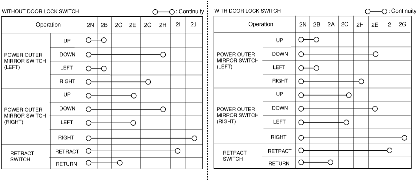
With Retractable outer mirror
1. Disconnect the negative battery cable. (See NEGATIVE BATTERY CABLE DISCONNECTION/CONNECTION [SKYACTIV-G 2.0, SKYACTIV-G 2.5].) (See NEGATIVE BATTERY CABLE DISCONNECTION/CONNECTION [SKYACTIV-G 2.0, SKYACTIV-G 2.5 (WITHOUT i-stop)].) (See NEGATIVE BATTERY CABLE DISCONNECTION/CONNECTION [SKYACTIV-D 2.2].)
2. Remove the power outer mirror switch. (See POWER OUTER MIRROR SWITCH REMOVAL/INSTALLATION.)
3. Verify that the continuity between the power outer mirror switch terminals is as indicated in the table.
am6zzw00014501
|
am6zzw00014567
|
4. Connect the negative battery cable. (See NEGATIVE BATTERY CABLE DISCONNECTION/CONNECTION [SKYACTIV-G 2.0, SKYACTIV-G 2.5].) (See NEGATIVE BATTERY CABLE DISCONNECTION/CONNECTION [SKYACTIV-G 2.0, SKYACTIV-G 2.5 (WITHOUT i-stop)].) (See NEGATIVE BATTERY CABLE DISCONNECTION/CONNECTION [SKYACTIV-D 2.2].)
5. Measure the voltage at each terminal.
|
Terminal |
Signal name |
Connected to |
Measurement condition |
Voltage (V) |
Inspection item (s) |
|---|---|---|---|---|---|
|
2A*2
|
Retract signal
|
Power outer mirror (LH/RH)
|
While outer mirror glass (RH) is moving downward or towards right
|
B+
|
• Related wiring harness
• Power outer mirror
|
|
Other
|
1.0 or less
|
||||
|
2B
|
Right/down signal
|
Power outer mirror (LH)
|
While outer mirror glass (LH) is moving downward or towards right
|
B+
|
• Related wiring harness
• Power outer mirror
|
|
Other
|
1.0 or less
|
||||
|
2C
|
Retract signal*1
|
Power outer mirror (LH/RH)
|
While power outer mirror (LH/RH) is retracting
|
B+
|
• Related wiring harness
• Power outer mirror
|
|
Other
|
1.0 or less
|
||||
|
Right/down signal*2
|
Power outer mirror (RH)
|
While outer mirror glass (RH) is moving downward or towards right
|
B+
|
||
|
Other
|
1.0 or less
|
||||
|
2E
|
Right/down signal*1
|
Power outer mirror (RH)
|
While outer mirror glass (RH) is moving downward or towards right
|
B+
|
• Related wiring harness
• Power outer mirror
|
|
Other
|
1.0 or less
|
||||
|
Up signal*2
|
Power outer mirror (LH/RH)
|
While outer mirror glass (LH/RH) is moving upward
|
B+
|
||
|
Other
|
1.0 or less
|
||||
|
2G
|
Left signal
|
Power outer mirror (LH)*1
|
While outer mirror glass (LH) is moving towards left
|
B+
|
• Related wiring harness
• Power outer mirror
|
|
Other
|
1.0 or less
|
||||
|
Power outer mirror (RH)*2
|
While outer mirror glass (RH) is moving towards left
|
B+
|
|||
|
Other
|
1.0 or less
|
||||
|
2H
|
Up signal*1
|
Power outer mirror (LH/RH)
|
While outer mirror glass (LH/RH) is moving upward
|
B+
|
• Related wiring harness
• Power outer mirror
|
|
Other
|
1.0 or less
|
||||
|
Left signal*2
|
Power outer mirror (LH)
|
While outer mirror glass (LH) is moving towards left
|
B+
|
||
|
Other
|
1.0 or less
|
||||
|
2I
|
Return signal
|
Power outer mirror (LH/RH)
|
While power outer mirror (LH/RH) is returning
|
B+
|
• Related wiring harness
• Power outer mirror
|
|
Other
|
1.0 or less
|
||||
|
2J*1
|
Left signal
|
Power outer mirror (RH)
|
While outer mirror glass (RH) is moving towards left
|
B+
|
• Related wiring harness
• Power outer mirror
|
|
Other
|
1.0 or less
|
||||
|
2N
|
GND
|
Body ground
|
Under any condition
|
1.0 or less
|
• Related wiring harness
|
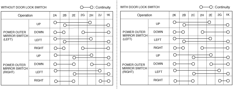
Without Retractable outer mirror
1. Disconnect the negative battery cable. (See NEGATIVE BATTERY CABLE DISCONNECTION/CONNECTION [SKYACTIV-G 2.0, SKYACTIV-G 2.5].) (See NEGATIVE BATTERY CABLE DISCONNECTION/CONNECTION [SKYACTIV-G 2.0, SKYACTIV-G 2.5 (WITHOUT i-stop)].) (See NEGATIVE BATTERY CABLE DISCONNECTION/CONNECTION [SKYACTIV-D 2.2].)
2. Remove the power outer mirror switch. (See POWER OUTER MIRROR SWITCH REMOVAL/INSTALLATION.)
3. Verify that the continuity between the power outer mirror switch terminals is as indicated in the table.
am6zzw00014465
|
am6zzw00014568
|
|
Terminal |
Signal name |
Connected to |
Measurement condition |
Voltage (V) |
Inspection item (s) |
|---|---|---|---|---|---|
|
1K
|
GND
|
Body ground
|
Under any condition
|
1.0 or less
|
• Related wiring harness
|
|
2B
|
Right/down signal
|
Power outer mirror (LH)
|
While outer mirror glass (LH) is moving downward or towards right
|
B+
|
• Related wiring harness
• Power outer mirror
|
|
Other
|
1.0 or less
|
||||
|
2C*2
|
Right/down signal
|
Power outer mirror (RH)
|
While outer mirror glass (RH) is moving downward or towards right
|
B+
|
• Related wiring harness
• Power outer mirror
|
|
Other
|
1.0 or less
|
||||
|
2E
|
Right/down signal*1
|
Power outer mirror (RH)
|
While outer mirror glass (RH) is moving downward or towards right
|
B+
|
• Related wiring harness
• Power outer mirror
|
|
Other
|
1.0 or less
|
||||
|
Up signal*2
|
Power outer mirror (LH/RH)
|
While power outer mirror (LH/RH) is returning
|
B+
|
||
|
Other
|
1.0 or less
|
||||
|
2G
|
Left signal
|
Power outer mirror (LH)*1
|
While outer mirror glass (LH) is moving towards left
|
B+
|
• Related wiring harness
• Power outer mirror
|
|
Other
|
1.0 or less
|
||||
|
Power outer mirror (RH)*2
|
While outer mirror glass (RH) is moving towards left
|
B+
|
• Related wiring harness
• Power outer mirror
|
||
|
Other
|
1.0 or less
|
||||
|
2H
|
Up signal*1
|
Power outer mirror (LH/RH)
|
While outer mirror glass (LH/RH) is moving upward
|
B+
|
• Related wiring harness
• Power outer mirror
|
|
Other
|
1.0 or less
|
||||
|
Left signal*2
|
Power outer mirror (LH)
|
While outer mirror glass (LH) is moving towards left
|
B+
|
||
|
Other
|
1.0 or less
|
||||
|
2I
|
Return signal
|
Power outer mirror (LH/RH)
|
While power outer mirror (LH/RH) is returning
|
B+
|
• Related wiring harness
• Power outer mirror
|
|
Other
|
1.0 or less
|
||||
|
2J*1
|
Left signal
|
Power outer mirror (RH)
|
While outer mirror glass (RH) is moving towards left
|
B+
|
• Related wiring harness
• Power outer mirror
|
|
Other
|
1.0 or less
|
||||
|
2K
|
GND
|
Body ground
|
Under any condition
|
1.0 or less
|
• Related wiring harness
|