Note
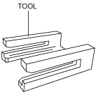
• With the purchase of an instrument cluster or the active driving display component, the tool used for the wiring harness removal is provided.
am6zzw00013742
|
ACTIVE DRIVING DISPLAY REMOVAL/INSTALLATION
id092200103700
am6zzw00013742
|
Replacing Active Driving Display as Single Component
1. Disconnect the negative battery cable. (See NEGATIVE BATTERY CABLE DISCONNECTION/CONNECTION [SKYACTIV-D 2.2].)(See NEGATIVE BATTERY CABLE DISCONNECTION/CONNECTION [SKYACTIV-G 2.0, SKYACTIV-G 2.5].)(See NEGATIVE BATTERY CABLE DISCONNECTION/CONNECTION [SKYACTIV-G 2.0, SKYACTIV-G 2.5 (WITHOUT i-stop)].)
2. Remove the following parts:
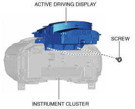
3. Remove the screws.
am6zzw00013743
|
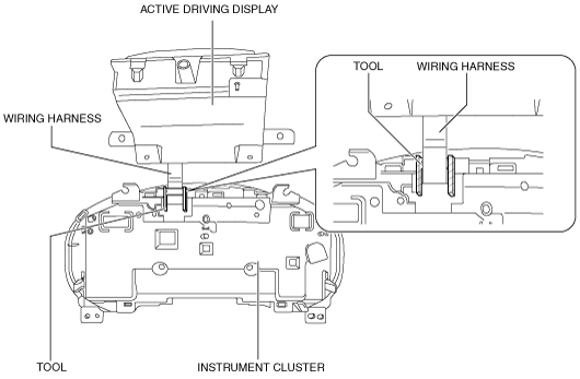
4. Insert the tool into the position shown in the figure, pull the wiring harness in the direction of the arrow, and disconnect the wiring harness from the instrument cluster.
am6zzw00013744
|
5. Remove the active driving display.
6. Install in the reverse order of removal.
Replacing Combiner
1. Refer to ACTIVE DRIVING DISPLAY INSPECTION and stop the combiner at an angle of 10 degrees. (See ACTIVE DRIVING DISPLAY INSPECTION.)
2. Switch the ignition off.
3. Disconnect the negative battery cable. (See NEGATIVE BATTERY CABLE DISCONNECTION/CONNECTION [SKYACTIV-D 2.2].)(See NEGATIVE BATTERY CABLE DISCONNECTION/CONNECTION [SKYACTIV-G 2.0, SKYACTIV-G 2.5].)(See NEGATIVE BATTERY CABLE DISCONNECTION/CONNECTION [SKYACTIV-G 2.0, SKYACTIV-G 2.5 (WITHOUT i-stop)].)
4. Remove the following parts:
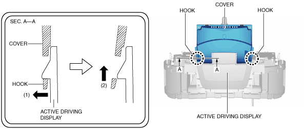
5. Lift up the cover hook in the direction of arrow (1) shown in the figure, move it in the direction of arrow (2), and detach the cover hooks from the active driving display.
am6zzw00013745
|
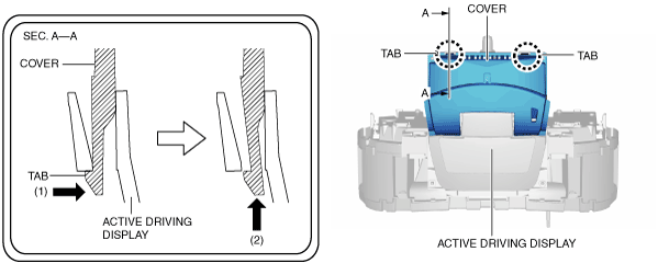
6. Press the cover tab in the direction of arrow (1) shown in the figure, move it in the direction of arrow (2), and detach the cover tabs from the active driving display.
am6zzw00013746
|
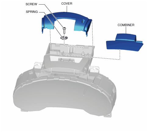
7. Remove the cover.
am6zzw00013747
|
8. Remove the screw.
9. Remove the spring.
10. Remove the combiner. (See Combiner assembly note.)
11. Install in the reverse order of removal.
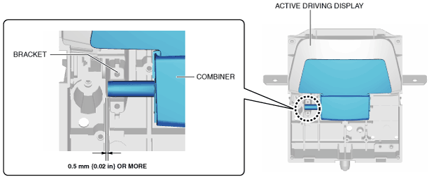
Combiner assembly note
am6zzw00013748
|