 |
am6zzb00000353
FRONT SIDE FRAME (PARTIAL CUTTING) REMOVAL [PANEL REPLACEMENT]
id098008742100
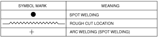
Symbol Mark
am6zzb00000353
|
Removal Procedure
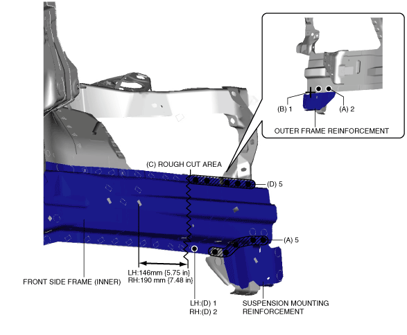
1. Drill the 7 locations indicated by (A) shown in the figure.
am6zzb00000354
|
2. Grind the 1 location indicated by (B) shown in the figure, then remove the suspension mounting reinforcement and outer frame reinforcement.
3. Rough cut the location indicated by (C) shown in the figure.
4. Drill the 6 locations (LH), 7 locations (RH) indicated by (D) shown in the figure, then remove the front side frame (inner).
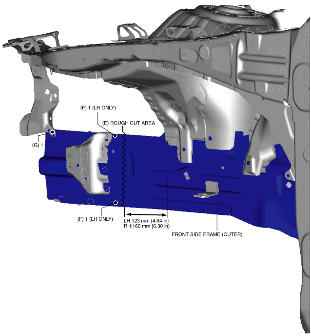
5. Rough cut the location indicated by (E) shown in the figure.
am6zzb00000355
|
6. Drill the 2 locations indicated by (F) shown in the figure. (LH only)
7. Drill the 1 location indicated by (G) shown in the figure, then remove the front side frame (outer).