ON-BOARD DIAGNOSTIC [BLIND SPOT MONITORING (BSM) CONTROL MODULE (Australian specs.)]
id1502006955b7
Outline
• The on-board diagnostic function consists of the following functions:
-
― A malfunction detection function, which detects overall malfunctions in the blind spot monitoring (BSM) system-related parts.
― A memory function, which stores detected DTCs.
― A display function, which indicates malfunction locations and status via DTC output.
― A PID/data monitoring function, which reads out specific input/output signals and verifies the input/output condition.
• Using the Mazda Modular Diagnostic System (M-MDS), DTCs can be read out and deleted, and the PID/data monitoring function can be activated.
Malfunction detection function
• Detects malfunctions in input/output signals.
• If a malfunction occurs, the blind spot monitoring (BSM) control module (LH) or (RH) records the malfunction as a DTC. A recorded DTC can be read by the Mazda Modular Diagnostic System (M-MDS).
DTC table
Blind spot monitoring (BSM) control module (LH)
×: Applicable
—: Not applicable
|
DTC No.
|
Blind spot monitoring (BSM) OFF Indication*2/blind spot monitoring (BSM) OFF indicator light*3
|
Description
|
Fail-safe
|
Drive cycle
|
Self test type*1
|
Memory function
|
|
B118C:11
|
Display*2/On*3
|
Blind spot monitoring (BSM) indicator light (LH) circuit malfunction
|
×
|
—
|
C, D
|
×
|
|
B118C:15
|
Display*2/On*3
|
Blind spot monitoring (BSM) indicator light (LH) circuit malfunction
|
×
|
—
|
C, D
|
×
|
|
U0001:88
|
Display*2/On*3
|
Module communication error (HS-CAN)
|
×
|
—
|
C, D
|
×
|
|
U0100:00
|
Display*2/On*3
|
Communication error with PCM
|
×
|
—
|
C, D
|
×
|
|
U0131:00
|
Display*2/On*3
|
Communication error with EPS control module
|
×
|
—
|
C, D
|
×
|
|
U0155:00
|
Display*2/On*3
|
Communication error with instrument cluster
|
×
|
—
|
C, D
|
×
|
|
U0214:00
|
Display*2/On*3
|
Communication error with start stop unit
|
×
|
—
|
C, D
|
×
|
|
U0233:00
|
Display*2/On*3
|
Communication error with blind spot monitoring (BSM) control module (RH)
|
×
|
—
|
C, D
|
×
|
|
U0401:68
|
Display*2/On*3
|
Error signal received from PCM
|
×
|
—
|
C, D
|
×
|
|
U0420:68
|
Display*2/On*3
|
Error signal received from EPS control module
|
×
|
—
|
C, D
|
×
|
|
U0423:68
|
Display*2/On*3
|
Error signal received from instrument cluster
|
×
|
—
|
C, D
|
×
|
|
U0515:68
|
Display*2/On*3
|
Error signal received from start stop unit
|
×
|
—
|
C, D
|
×
|
|
U2300:54
|
Display*2/On*3
|
Configuration signal not received
|
×
|
—
|
C, D
|
×
|
|
U2300:56
|
Display*2/On*3
|
Instrument cluster configuration error
|
×
|
—
|
C, D
|
×
|
|
U2300:64
|
Display*2/On*3
|
Configuration data unmatched with instrument cluster
|
×
|
—
|
C, D
|
×
|
|
U3000:01
|
Display*2/On*3
|
Electrical malfunction inside blind spot monitoring (BSM) control module
|
×
|
—
|
C, D
|
×
|
|
U3000:09
|
Display*2/On*3
|
Blind spot monitoring (BSM) control module internal malfunction
|
×
|
—
|
C, D
|
×
|
|
U3000:54
|
Display*2/On*3
|
Radar performance malfunction
|
×
|
—
|
C, D
|
×
|
|
U3000:97
|
Display*2/On*3
|
Radar performance malfunction
|
×
|
—
|
C, D
|
×
|
|
U3003:04
|
Display*2/On*3
|
Instrument cluster configuration error
|
×
|
—
|
C, D
|
×
|
|
U3003:16
|
Display*2/On*3
|
Blind spot monitoring (BSM) control module low power supply voltage input (less than 8.2 V)
|
×
|
—
|
C, D
|
×
|
|
U3003:17
|
Display*2/On*3
|
Blind spot monitoring (BSM) control module high power supply voltage input (16.8 V or more)
|
×
|
—
|
C, D
|
×
|
*1 :C: CMDTC self test, D: ODDTC self test
*2 :Type A instrument cluster
*3 :Type B instrument cluster
Blind spot monitoring (BSM) control module (RH)
×: Applicable
—: Not applicable
|
DTC No.
|
Blind spot monitoring (BSM) OFF Indication*2/blind spot monitoring (BSM) OFF indicator light*3
|
Description
|
Fail-safe
|
Drive cycle
|
Self test type*1
|
Memory function
|
|
B118D:11
|
Display*2/On*3
|
Blind spot monitoring (BSM) indicator light (RH) circuit malfunction
|
×
|
—
|
C, D
|
×
|
|
B118D:15
|
Display*2/On*3
|
Blind spot monitoring (BSM) indicator light (RH) circuit malfunction
|
×
|
—
|
C, D
|
×
|
|
U0001:88
|
Display*2/On*3
|
Module communication error (HS-CAN)
|
×
|
—
|
C, D
|
×
|
|
U0100:00
|
Display*2/On*3
|
Communication error with PCM
|
×
|
—
|
C, D
|
×
|
|
U0131:00
|
Display*2/On*3
|
Communication error with EPS control module
|
×
|
—
|
C, D
|
×
|
|
U0155:00
|
Display*2/On*3
|
Communication error with instrument cluster
|
×
|
—
|
C, D
|
×
|
|
U0214:00
|
Display*2/On*3
|
Communication error with start stop unit
|
×
|
—
|
C, D
|
×
|
|
U0232:00
|
Display*2/On*3
|
Communication error with blind spot monitoring (BSM) control module (LH)
|
×
|
—
|
C, D
|
×
|
|
U0401:68
|
Display*2/On*3
|
Error signal received from PCM
|
×
|
—
|
C, D
|
×
|
|
U0420:68
|
Display*2/On*3
|
Error signal received from EPS control module
|
×
|
—
|
C, D
|
×
|
|
U0423:68
|
Display*2/On*3
|
Error signal received from instrument cluster
|
×
|
—
|
C, D
|
×
|
|
U0515:68
|
Display*2/On*3
|
Error signal received from start stop unit
|
×
|
—
|
C, D
|
×
|
|
U2300:54
|
Display*2/On*3
|
Configuration signal not received
|
×
|
—
|
C, D
|
×
|
|
U2300:56
|
Display*2/On*3
|
Instrument cluster configuration error
|
×
|
—
|
C, D
|
×
|
|
U2300:64
|
Display*2/On*3
|
Configuration data unmatched with instrument cluster
|
×
|
—
|
C, D
|
×
|
|
U3000:01
|
Display*2/On*3
|
Electrical malfunction inside blind spot monitoring (BSM) control module
|
×
|
—
|
C, D
|
×
|
|
U3000:09
|
Display*2/On*3
|
Blind spot monitoring (BSM) control module internal malfunction
|
×
|
—
|
C, D
|
×
|
|
U3000:54
|
Display*2/On*3
|
Radar performance malfunction
|
×
|
—
|
C, D
|
×
|
|
U3000:97
|
Display*2/On*3
|
Radar performance malfunction
|
×
|
—
|
C, D
|
×
|
|
U3003:04
|
Display*2/On*3
|
Instrument cluster configuration error
|
×
|
—
|
C, D
|
×
|
|
U3003:16
|
Display*2/On*3
|
Blind spot monitoring (BSM) control module low power supply voltage input (less than 8.2 V)
|
×
|
—
|
C, D
|
×
|
|
U3003:17
|
Display*2/On*3
|
Blind spot monitoring (BSM) control module high power supply voltage input (16.8 V or more)
|
×
|
—
|
C, D
|
×
|
*1 :C: CMDTC self test, D: ODDTC self test
*2 :Type A instrument cluster
*3 :Type B instrument cluster
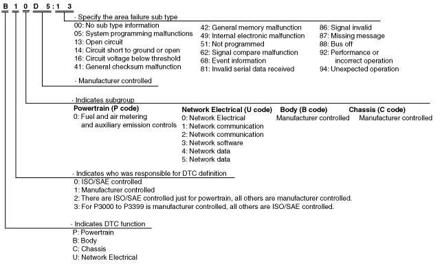
DTC 7-digit code definition
-
• When related systems or components have failed, the CM stores the DTC of the malfunctioning part in the CM memory, and allows for the retrieval of the store data using scanning tool when necessary. The DTCs are indicated using seven digits. Each digit indicates the following.
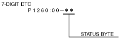
Status byte for DTC
-
• The two digits (two digits after hyphen (-)) after the 7-digit DTC.
• A code which indicates the pending code, current/past malfunction status, or warning illumination status.
• Can be read by performing a CMDTC self-test using the Mazda Modular Diagnostic System (M-MDS).
• For details on the status byte, refer to the explanation on the Mazda Modular Diagnostic System (M-MDS) when reading the DTC.
Detection condition for the applicable DTC
Blind spot monitoring (BSM) control module (LH)
|
DTC No.
|
Description
|
Detection condition
|
|
B118C:11
|
Blind spot monitoring (BSM) indicator light (LH) circuit malfunction
|
• Blind spot monitoring (BSM) control module (LH) performs measurement at 0.01 s intervals and a short to ground in the blind spot monitoring (BSM) indicator light (LH) circuit is detected 48 times continuously.
|
|
B118C:15
|
Blind spot monitoring (BSM) indicator light (LH) circuit malfunction
|
• Blind spot monitoring (BSM) control module (LH) performs measurement at 0.01 s intervals and a short circuit to power supply or open circuit in the blind spot monitoring (BSM) indicator light (LH) circuit is detected 48 times continuously.
|
|
U0001:88
|
Module communication error (HS-CAN)
|
• Blind spot monitoring (BSM) control module detected a CAN bus communication line (HS-CAN) malfunction for 0.4 s or more.
|
|
U0100:00
|
Communication error with PCM
|
• Blind spot monitoring (BSM) control module cannot receive a CAN signal from the PCM for 1.5 s or more.
|
|
U0131:00
|
Communication error with EPS control module
|
• Blind spot monitoring (BSM) control module cannot receive a CAN signal from the EPS control module for 1.5 s or more.
|
|
U0155:00
|
Communication error with instrument cluster
|
• Blind spot monitoring (BSM) control module cannot receive a CAN signal from the instrument cluster.
|
|
U0214:00
|
Communication error with start stop unit
|
• Blind spot monitoring (BSM) control module cannot receive a CAN signal from the start stop unit for 1.5 s or more.
|
|
U0233:00
|
Communication error with blind spot monitoring (BSM) control module (RH)
|
• No communication between blind spot monitoring (BSM) control module (LH) and (RH) for 1 s or more.
|
|
U0401:68
|
Error signal received from PCM
|
• Blind spot monitoring (BSM) control module receives the error signal from the PCM for 1 s or more.
|
|
U0420:68
|
Error signal received from EPS control module
|
• Blind spot monitoring (BSM) control module receives the error signal from the EPS control module for 1 s or more.
|
|
U0423:68
|
Error signal received from instrument cluster
|
• Blind spot monitoring (BSM) control module receives the error signal from the instrument cluster for 1 s or more.
|
|
U0515:68
|
Error signal received from start stop unit
|
• Blind spot monitoring (BSM) control module receives the error signal from the start stop unit for 1 s or more.
|
|
U2300:54
|
Configuration signal not received
|
• Blind spot monitoring (BSM) control module cannot receive the configuration signal it is supposed to receive.
|
|
U2300:56
|
Instrument cluster configuration error
|
• Instrument cluster configuration error (signal error) detected.
|
|
U2300:64
|
Configuration data unmatched with instrument cluster
|
• Configuration data of the blind spot monitoring (BSM) control module and instrument cluster are not matched.
|
|
U3000:01
|
Electrical malfunction inside blind spot monitoring (BSM) control module
|
• Blind spot monitoring (BSM) control module is detected an electrical malfunction inside.
|
|
U3000:09
|
Blind spot monitoring (BSM) control module internal malfunction
|
• Blind spot monitoring (BSM) control module detected a malfunction inside the voltage control oscillator.
|
|
U3000:54
|
Radar performance malfunction
|
• Blind spot monitoring (BSM) control module detected malfunction in misalignment.
|
|
U3000:97
|
Radar performance malfunction
|
• Blind spot monitoring (BSM) control module internal radar sensor sensitivity is decreased.
• Blind spot monitoring (BSM) control module internal radar sensor axis is deviated.
|
|
U3003:04
|
Instrument cluster configuration error
|
• Instrument cluster configuration error detected.
|
|
U3003:16
|
Blind spot monitoring (BSM) control module low power supply voltage input (less than 8.2 V)
|
• Blind spot monitoring (BSM) control module power supply voltage of less than 8.2 V is detected for 2 s or more.
|
|
U3003:17
|
Blind spot monitoring (BSM) control module high power supply voltage input (16.8 V or more)
|
• Blind spot monitoring (BSM) control module power supply voltage of 16.8 V or more is detected for 2 s or more.
|
Blind spot monitoring (BSM) control module (RH)
|
DTC No.
|
Description
|
Detection condition
|
|
B118D:11
|
Blind spot monitoring (BSM) indicator light (RH) circuit malfunction
|
• Blind spot monitoring (BSM) control module (RH) performs measurement at 0.01 s intervals and a short to ground in the blind spot monitoring (BSM) indicator light (RH) circuit is detected 48 times continuously.
|
|
B118D:15
|
Blind spot monitoring (BSM) indicator light (RH) circuit malfunction
|
• Blind spot monitoring (BSM) control module (RH) performs measurement at 0.01 s intervals and a short circuit to power supply or open circuit in the blind spot monitoring (BSM) indicator light (RH) circuit is detected 48 times continuously.
|
|
U0001:88
|
Module communication error (HS-CAN)
|
• Blind spot monitoring (BSM) control module detected a CAN bus communication line (HS-CAN) malfunction for 0.4 s or more.
|
|
U0100:00
|
Communication error with PCM
|
• Blind spot monitoring (BSM) control module cannot receive a CAN signal from the PCM for 1.5 s or more.
|
|
U0131:00
|
Communication error with EPS control module
|
• Blind spot monitoring (BSM) control module cannot receive a CAN signal from the EPS control module for 1.5 s or more.
|
|
U0155:00
|
Communication error with instrument cluster
|
• Blind spot monitoring (BSM) control module cannot receive a CAN signal from the instrument cluster.
|
|
U0214:00
|
Communication error with start stop unit
|
• Blind spot monitoring (BSM) control module cannot receive a CAN signal from the start stop unit for 1.5 s or more.
|
|
U0232:00
|
Communication error with blind spot monitoring (BSM) control module (LH)
|
• No communication between blind spot monitoring (BSM) control module (LH) and (RH) for 1 s or more.
|
|
U0401:68
|
Error signal received from PCM
|
• Blind spot monitoring (BSM) control module receives the error signal from the PCM for 1 s or more.
|
|
U0420:68
|
Error signal received from EPS control module
|
• Blind spot monitoring (BSM) control module receives the error signal from the EPS control module for 1 s or more.
|
|
U0423:68
|
Error signal received from instrument cluster
|
• Blind spot monitoring (BSM) control module receives the error signal from the instrument cluster for 1 s or more.
|
|
U0515:68
|
Error signal received from start stop unit
|
• Blind spot monitoring (BSM) control module receives the error signal from the start stop unit for 1 s or more.
|
|
U2300:54
|
Configuration signal not received
|
• Blind spot monitoring (BSM) control module cannot receive the configuration signal it is supposed to receive.
|
|
U2300:56
|
Instrument cluster configuration error
|
• Instrument cluster configuration error (signal error) detected.
|
|
U2300:64
|
Configuration data unmatched with instrument cluster
|
• Configuration data of the blind spot monitoring (BSM) control module and instrument cluster are not matched.
|
|
U3000:01
|
Electrical malfunction inside blind spot monitoring (BSM) control module
|
• Blind spot monitoring (BSM) control module is detected an electrical malfunction inside.
|
|
U3000:09
|
Blind spot monitoring (BSM) control module internal malfunction
|
• Blind spot monitoring (BSM) control module detected a malfunction inside the voltage control oscillator.
|
|
U3000:54
|
Radar performance malfunction
|
• Blind spot monitoring (BSM) control module detected malfunction in misalignment.
|
|
U3000:97
|
Radar performance malfunction
|
• Blind spot monitoring (BSM) control module internal radar sensor sensitivity is decreased.
• Blind spot monitoring (BSM) control module internal radar sensor axis is deviated.
|
|
U3003:04
|
Instrument cluster configuration error
|
• Instrument cluster configuration error detected.
|
|
U3003:16
|
Blind spot monitoring (BSM) control module low power supply voltage input (less than 8.2 V)
|
• Blind spot monitoring (BSM) control module power supply voltage of less than 8.2 V is detected for 2 s or more.
|
|
U3003:17
|
Blind spot monitoring (BSM) control module high power supply voltage input (16.8 V or more)
|
• Blind spot monitoring (BSM) control module power supply voltage of 16.8 V or more is detected for 2 s or more.
|
Snapshot Data
-
Note
-
• The blind spot monitoring (BSM) control module (LH) or (RH) stores the following two types of snapshot data (vehicle information) when a DTC is detected and displays them in the Mazda Modular Diagnostic System (M-MDS).
-
― Vehicle information detected by blind spot monitoring (BSM) control module (LH) or (RH)
― Vehicle information detected by instrument cluster and received by blind spot monitoring (BSM) control module (LH) or (RH) via CAN communication
• The data for all DTCs currently detected is stored.
—: Not applicable
|
Snapshot data item
|
Unit
|
Data contents
|
Data read/use method
|
Corresponding data monitor items
|
|
AAT
|
°C
|
°F
|
Ambient temperature
|
—
|
—
|
|
APP_STATUS
|
Accelerator Pedal Off/Under20%/Over20%/FAIL
|
Accelerator pedal position status
|
—
|
—
|
|
CFG_STATUS
|
Config Complete/Not Configured/Config Error
|
Instrument cluster configuration status
|
—
|
—
|
|
ECT_STATUS
|
Under 0 degrees C/0 - Under 80 degrees C/Over 80 degrees C/FAIL
|
Engine coolant temperature status
|
—
|
—
|
|
IC_VPWR
|
V
|
Instrument cluster power supply voltage
|
• The blind spot monitoring (BSM) control module (LH) or (RH) constantly receives the power supply voltage value of the instrument cluster sent via CAN communication from the instrument cluster.
• If a DTC is detected, the blind spot monitoring (BSM) control module (LH) or (RH) records the power supply voltage of the instrument cluster when the DTC was detected, and it is displayed in the Mazda Modular Diagnostic System (M-MDS).
|
VPWR*1
|
|
IG-ON_TIMER
|
hh:mm:ss*2
|
Elapsed time since ignition was switched ON (engine off or on)
-
Note
-
• The instrument cluster records the elapsed time since the ignition was switched ON (engine off or on).
|
• The blind spot monitoring (BSM) control module (LH) or (RH) constantly receives the elapsed time since the ignition was switched ON (engine off or on) sent via CAN communication from the instrument cluster.
• If a DTC is detected, the blind spot monitoring (BSM) control module (LH) or (RH) records the elapsed time since the ignition was switched ON (engine off or on) when the DTC was detected, and it is displayed in the Mazda Modular Diagnostic System (M-MDS).
|
—
|
|
PWR_MODE_KEY
|
Key Out/Key Recently Out (Position 0)/Accessory (Position 1)/Post Ignition (Position 2)/Ignition On (Position 2)/Running (Position 2)/Running - Starting
|
• Key Out: Ignition switched off
• Key Recently Out (Position 0): Elapsed time within 3 s since ignition was switched off
• Accessory (Position 1): Ignition is switched to ACC
• Post Ignition (Position 2): Elapsed time within 3 s since ignition was switched ON (engine off or on)
• Ignition On (Position 2): Ignition switched ON (engine off)
• Running (Position 2): Ignition switched ON (engine on)
• Running - Starting: Cranking condition
|
• The blind spot monitoring (BSM) control module (LH) or (RH) constantly receives the ignition switch status sent via CAN communication from the instrument cluster.
• If a DTC is detected, the blind spot monitoring (BSM) control module (LH) or (RH) records the ignition switch status when the DTC was detected, and it is displayed in the Mazda Modular Diagnostic System (M-MDS).
|
—
|
|
RPM_STATUS
|
Engine Stop/Under1500rpm/Over1500rpm/FAIL
|
Engine speed status
|
• The blind spot monitoring (BSM) control module (LH) or (RH) constantly receives the engine speed sent via CAN communication from the instrument cluster.
• If a DTC is detected, the blind spot monitoring (BSM) control module (LH) or (RH) records the engine speed when the DTC was detected, and it is displayed in the Mazda Modular Diagnostic System (M-MDS).
|
TACHOMTR*1
|
|
SHIFT_STATUS
|
P/N/D/R/FAIL
|
Selector lever position status
|
• The blind spot monitoring (BSM) control module (LH) or (RH) constantly receives the selector lever position sent via CAN communication from the instrument cluster.
• If a DTC is detected, the blind spot monitoring (BSM) control module (LH) or (RH) records the selector lever position when the DTC was detected, and it is displayed in the Mazda Modular Diagnostic System (M-MDS).
|
—
|
|
TOTAL_DIST
|
km
|
Miles
|
Accumulated total traveled distance from completion of vehicle until blind spot monitoring (BSM) control module (LH) or (RH) detects DTC (Odometer value in instrument cluster)
|
The total traveled distance from which the blind spot monitoring (BSM) control module (LH) or (RH) detects DTCs to the present can be calculated by performing the following procedure.
1. Verify the odometer value in the instrument cluster.
2. Verify the snapshot data item TOTAL_DIST.
3. Subtract 2 from 1.
|
—
|
|
TOTAL_TIME
|
hh:mm:ss*2
|
Accumulated total elapsed time since vehicle completion until blind spot monitoring (BSM) control module (LH) or (RH) detects a DTC
-
Note
-
• When the ROOM fuse is removed, and the ignition is switched off, the time is not included in the elapsed time.
|
The elapsed time from which the blind spot monitoring (BSM) control module (LH) or (RH) detects DTCs to the present can be calculated by performing the following procedure.
1. Verify the instrument cluster PID item TOTAL_TIME.
2. Verify the snapshot data item TOTAL_TIME.
3. Subtract 2 from 1.
|
TOTAL_TIME*1
|
|
VPWR
|
V
|
Blind spot monitoring control module (LH) or (RH) power supply voltage
|
—
|
VPWR_IG1
|
|
VSPD_STATUS
|
Stop/0-10km/h/Over10km/h/FAIL
|
Vehicle speed status
|
• The blind spot monitoring control module (LH) or (RH) constantly receives the vehicle speed sent via CAN communication from the instrument cluster.
• If a DTC is detected, the blind spot monitoring control module (LH) or (RH) records the vehicle speed when the DTC was detected, and it is displayed in the Mazda Modular Diagnostic System (M-MDS).
|
SPEEDOMTR*1
|
*2 :The seconds may be indicated after the decimal point.
Data Monitor Function
• With the PID/data monitor function, the input/output signal monitor items set in the blind spot monitoring (BSM) control module can be selected and read out in real-time.
• The items which can be selected are as follows.
Blind spot monitoring (BSM) control module (LH)
—: Not applicable
|
PID name
|
Unit/Status
|
Data contents
|
Inspection item(s)
|
|
DTC_CNT
|
—
|
Displays number of DTCs stored in the BSM control module (LH)
|
BSM control module (LH)
|
|
IL_MODE
|
Off/On
|
• Off: BSM OFF indicator light is illuminated in night mode.
• On: BSM OFF indicator light is illuminated in daytime mode.
|
BSM OFF indicator light (Instrument cluster)
|
|
RCTA_BUZZER
|
Off/On
|
• Off: RCTA buzzer does not sound.
• On: RCTA buzzer sounds.
|
Audio unit
|
|
RCTA_OFF_IL
|
Off/On
|
• Off: RCTA OFF indicator is turned off.
• On: RCTA OFF indicator is turned on.
|
Audio unit
|
|
RCTA_WARN
|
Off/On
|
• Off: RCTA warning indicator is turned off.
• On: RCTA warning indicator is turned on.
|
Audio unit
|
|
SHIFT_R
|
Not_R/R
|
ATX:
• Not_R: Selector lever is in position other than R.
• R: Selector lever is in R position.
MTX:
• Not_R: Shift lever is in position other than reverse.
• R: Shift lever is in reverse position.
|
ATX:
• Transaxle range sensor (TCM)
MTX:
• Back-up light switch
|
|
SWA_POS
|
° (deg)
|
Displays steering angle signal (estimated absolute angle)
• Steering wheel in neutral position: Near 0 degrees
• Steering wheel turned to left: Changes from 0 degrees to positive
• Steering wheel turned to right: Changes from 0 degrees to negative
|
• Perform the DTC inspection for the PCM, DSC HU/CM, and EPS CM, and if any DTC is displayed, repair the malfunctioning part according to the applicable DTC troubleshooting.
• After performing the DTC inspection, perform the following procedures:
-
― Switch the ignition off, and after 2 min or more have elapsed, switch the ignition ON (engine off or on).
― Start the engine and drive the vehicle 10 m {33 ft} or more in a straight line at a speed of 10 km/h {6.2 mph} or more.
― Stop the vehicle with the wheels in the straight-ahead position.
― Verify the operation condition of STR_AB_ANG using the Mazda Modular Diagnostic System (M-MDS).
• If an abnormal value is indicated again, replace the EPS CM.
|
|
VPWR_IG1
|
V
|
Displays BSM control module (LH) power supply voltage
|
• BSM control module (LH)
• IG1 relay
• Battery
|
|
VSPD
|
KPH, MPH
|
Displays vehicle speed
|
—
|
|
WRN_IND_L
|
Off/On
|
• Off: BSM indicator light (LH) is not illuminated.
• On: BSM indicator light (LH) is illuminated.
|
BSM indicator light (LH)
|
Blind spot monitoring (BSM) control module (RH)
—: Not applicable
|
PID name
|
Unit/Status
|
Data contents
|
Inspection item(s)
|
|
DTC_CNT
|
—
|
Displays number of DTCs stored in the BSM control module (RH)
|
BSM control module (RH)
|
|
IL_MODE
|
Off/On
|
• Off: BSM OFF indicator light is illuminated in night mode.
• On: BSM OFF indicator light is illuminated in daytime mode.
|
BSM OFF indicator light (Instrument cluster)
|
|
RCTA_OFF_IL
|
Off/On
|
• Off: RCTA OFF indicator is turned off.
• On: RCTA OFF indicator is turned on.
|
Audio unit
|
|
SHIFT_R
|
Not_R/R
|
ATX:
• Not_R: Selector lever is in position other than R.
• R: Selector lever is in R position.
MTX:
• Not_R: Shift lever is in position other than reverse.
• R: Shift lever is in reverse position.
|
ATX:
• Transaxle range sensor (TCM)
MTX:
• Back-up light switch
|
|
SWA_POS
|
° (deg)
|
Displays steering angle signal (estimated absolute angle)
• Steering wheel in neutral position: Near 0 degrees
• Steering wheel turned to left: Changes from 0 degrees to positive
• Steering wheel turned to right: Changes from 0 degrees to negative
|
• Perform the DTC inspection for the PCM, DSC HU/CM, and EPS CM, and if any DTC is displayed, repair the malfunctioning part according to the applicable DTC troubleshooting.
• After performing the DTC inspection, perform the following procedures:
-
― Switch the ignition off, and after 2 min or more have elapsed, switch the ignition ON (engine off or on).
― Start the engine and drive the vehicle 10 m {33 ft} or more in a straight line at a speed of 10 km/h {6.2 mph} or more.
― Stop the vehicle with the wheels in the straight-ahead position.
― Verify the operation condition of STR_AB_ANG using the Mazda Modular Diagnostic System (M-MDS).
• If an abnormal value is indicated again, replace the EPS CM.
|
|
VPWR_IG1
|
V
|
Displays BSM control module (RH) power supply voltage
|
• BSM control module (RH)
• IG1 relay
• Battery
|
|
VSPD
|
KPH, MPH
|
Displays vehicle speed
|
—
|
|
WRN_IND_R
|
Off/On
|
• Off: BSM indicator light (RH) is not illuminated.
• On: BSM indicator light (RH) is illuminated.
|
BSM indicator light (RH)
|
Simulation function
• The simulation function drives the output parts set in the blind spot monitoring (BSM) control module regardless of the blind spot monitoring (BSM) control module control condition.
• The items which can be selected are as follows.
Blind spot monitoring (BSM) control module (LH)
—: Not applicable
|
Command name
|
Unit/Operation
|
Data contents
|
Output part name
|
|
Buzzer
|
On/Off
|
• On: Operates BSM warning alarm.
• Off: Stops BSM warning alarm.
|
BSM warning alarm (Instrument cluster)
|
|
BSM_OFF_IL
|
Off/On
|
• Off: Turn off BSM OFF indicator.
• On: Illuminates BSM OFF indicator.
|
Instrument cluster
|
|
IL_MODE
|
Off/On
|
-
Note
-
• Use in conjunction with WRN_IND_L item.
• Off: Illuminates BSM OFF indicator light in night mode.
• On: Illuminates BSM OFF indicator light in daytime mode.
|
BSM OFF indicator light (Instrument cluster)
|
|
RCTA_BUZZER
|
Off/On
|
• Off: RCTA buzzer does not sound.
• On: RCTA buzzer sounds.
|
Center display
|
|
VSPD
|
OFF/ON
|
• OFF: Does not input vehicle speed.
• ON: Inputs vehicle speed of 34 km/h {21 mph}.
|
BSM control module (LH)
|
|
WRN_IND_L
|
Off/On
|
• Off: Turns off BSM indicator light (LH).
• On: Illuminates BSM indicator light (LH).
|
BSM indicator light (LH)
|
Blind spot monitoring (BSM) control module (RH)
—: Not applicable
|
Command name
|
Unit/Operation
|
Data contents
|
Output part name
|
|
IL_MODE
|
Off/On
|
-
Note
-
• Use in conjunction with WRN_IND_R item.
• Off: Illuminates BSM OFF indicator light in night mode.
• On: Illuminates BSM OFF indicator light in daytime mode.
|
BSM OFF indicator light (Instrument cluster)
|
|
RCTA_BUZZER
|
Off/On
|
• Off: RCTA buzzer does not sound.
• On: RCTA buzzer sounds.
|
Center display
|
|
VSPD
|
OFF/ON
|
• OFF: Does not input vehicle speed.
• ON: Inputs vehicle speed of 34 km/h {21 mph}.
|
BSM control module (RH)
|
|
WRN_IND_R
|
Off/On
|
• Off: Turns off BSM indicator light (RH).
• On: Illuminates BSM indicator light (RH).
|
BSM indicator light (RH)
|