|
bem5ze00000157
TIMING CHAIN ASSEMBLY [MZR-CD 2.2]
id0110f2505600
1. Assemble in the order indicated in the table.
bem5ze00000157
|
|
1
|
Timing belt pulley
|
|
2
|
Timing chain
|
|
3
|
Timing chain guide No.2
|
|
4
|
Timing chain guide No.1
|
|
5
|
Timing chain tensioner arm
|
|
6
|
Timing chain tensioner
|
|
7
|
Front oil seal
|
|
8
|
Engine front cover
|
|
9
|
CKP sensor
|
|
10
|
CMP sensor
|
|
11
|
Cylinder head cover
|
|
12
|
Insulator
|
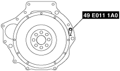
Crankshaft Sprocket Installation Note
1. Hold the crankshaft using the SST.
bem5ze00000155
|
2. Tighten the crankshaft sprocket installation bolt.
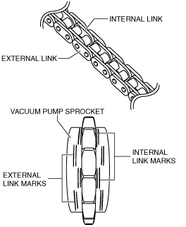
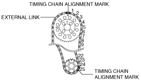
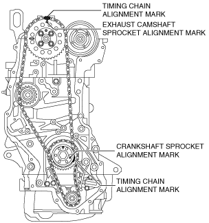
Timing Chain Installation Note
bem5ze00000176
|
am6zzw00004479
|
1. Set the timing chain with the timing chain alignment mark aligned with the exhaust camshaft sprocket alignment mark as well as the crankshaft sprocket alignment mark.
am6zzw00004302
|
Timing Chain Tensioner Installation Note
1. Install the timing chain tensioner.
2. Remove the wire or paper clip which has been installed to secure the plunger.
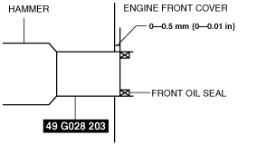
Front Oil Seal Installation Note
1. Apply clean engine oil to the oil seal lip.
2. Push the oil seal slightly in by hand.
3. Tap the oil seal in evenly using the SST and a hammer. The oil seal must be tapped in until it is flush with the edge of the engine front cover.
am6zzw00004185
|
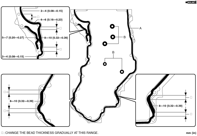
Engine Front Cover Installation Note
1. Apply sealant as shown in the figure.
am6zzw00004508
|
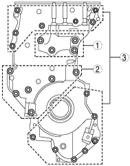
2. Tighten the bolts in the order shown in the figure.
am6zzw00004474
|
Crankshaft Position (CKP) Sensor Installation Note
1. Verify that the O-ring is not damaged.
2. Verify that there is no foreign material on the CKP sensor flange surface and the installation surface.
3. Apply a small amount of clean oil to the O-ring and the CKP sensor installation hole.
4. Press in the CKP sensor until the CKP sensor flange surface firmly adheres to the installation surface.
5. Verify that the O-ring is installed correctly to the sensor installation hole.
6. Tighten the bolt.
Camshaft Position (CMP) Sensor Installation Note
1. Verify that the O-ring is not damaged.
2. Verify that there is no foreign material on the CMP sensor flange surface and the installation surface.
3. Apply a small amount of clean oil to the O-ring and the CMP sensor installation hole.
4. Press in the CMP sensor until the CMP sensor flange surface firmly adheres to the installation surface.
5. Verify that the O-ring is installed correctly to the sensor installation hole.
6. Tighten the bolt.
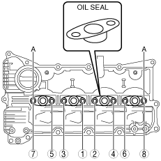
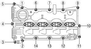
Cylinder Head Cover Installation Note
1. Apply sealant as shown in the figure.
am6zzw00004286
|
2. After temporarily tightening bolt A, tighten it in the order shown in the figure.
am6zzw00004219
|
3. Tighten the bolts in the order shown in the figure.
bem5ze00000161
|