DTC P062A:00 [MZR-CD 2.2]


id0102f3478600

DTC P062A:00

Suction control valve circuit range/performance malfunction

DETECTION CONDITION
•  The PCM monitors the suction control valve circuit current while the engine is running. If the PCM detects the circuit current is less than 1 A when the suction control valve is on, the PCM determines that there is a malfunction in the suction control valve circuit.
•  The PCM monitors the suction control valve circuit current while the engine is running. If the PCM detects circuit current is more than 1 A when the suction control valve is off, the PCM determines that there is the malfunction in the suction control valve circuit.
Monitoring conditions
―  Following conditions are met:
•  Battery voltage: 8—20 V
•  Engine speed: more than 0 rpm (at running)
•  Suction control valve driving duty: 100 %
Diagnostic support note
•  The MIL illuminates if the PCM detects the above malfunction condition in first drive cycle.
•  PENDING CODE is available if the PCM detects the above malfunction condition during the first drive cycle.
•  FREEZE FRAME DATA is available.
•  The DTC is stored in the PCM memory.
POSSIBLE CAUSE
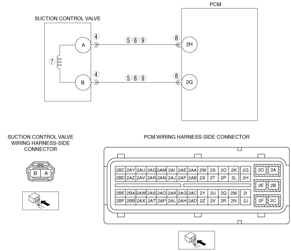
•  Suction control valve connector or terminal malfunction
•  Short to power supply in wiring harness between suction control valve terminal A and PCM terminal 2H
•  Short to power supply in wiring harness between suction control valve terminal B and PCM terminal 2G
•  Short to ground in wiring harness between suction control valve terminal A and PCM terminal 2H
•  Short to ground in wiring harness between suction control valve terminal B and PCM terminal 2G
•  Suction control valve malfunction
•  PCM connector or terminal malfunction
•  Open circuit in wiring harness between suction control valve terminal A and PCM terminal 2H
•  Open circuit in wiring harness between suction control valve terminal B and PCM terminal 2G
•  PCM malfunction

Diagnostic procedure

STEP

INSPECTION

ACTION

1
VERIFY FREEZE FRAME DATA HAS BEEN RECORDED
•  Has FREEZE FRAME DATA been recorded?
Yes
Go to the next step.
No
Record the FREEZE FRAME DATA on the repair order, then go to the next step.
2
VERIFY RELATED SERVICE INFORMATION
•  Verify related Service Information availability.
•  Is any related Service Information available?
Yes
Perform repair or diagnosis according to available Service Information.
•  If vehicle is not repaired, go to the next step.
No
Go to the next step.
3
VERIFY CURRENT SIGNAL STATUS: IS CONCERN INTERMITTENT OR CONSTANT?
•  Connect the M-MDS to the DLC-2.
•  Clear the DTC from the PCM memory using the M-MDS.
•  Start the engine.
•  Is the same DTC present?
Yes
Go to the next step.
No
Intermittent concern exists.
Perform the “INTERMITTENT CONCERN TROUBLESHOOTING”.
4
INSPECT POOR CONNECTION OF SUCTION CONTROL VALVE CONNECTOR
•  Switch the ignition to off.
•  Inspect for poor connection (such as damaged/pulled-out terminals, corrosion).
•  Is there any malfunction?
Yes
Repair or replace the suspected terminal, go to Step 9.
No
Go to the next step.
5
INSPECT SUCTION CONTROL VALVE CIRCUIT FOR SHORT TO POWER SUPPLY
•  Switch the ignition to ON (Engine off).
•  Inspected the voltage between the following terminals and body ground:
―  Suction control valve terminal A and body ground.
―  Suction control valve terminal B and body ground.
•  Is the voltage less than 1.0 V?
Yes
Go to the next step.
No
Repair or replace the wiring harness for a short to power supply, go to Step 10.
6
INSPECT SUCTION CONTROL VALVE CIRCUIT FOR A SHORT TO GROUND
•  Switch the ignition to off.
•  Inspect for continuity between the following terminals and body ground:
―  Suction control valve terminal A and body ground.
―  Suction control valve terminal B and body ground.
•  Is there continuity?
Yes
Repair or replace the wiring harness for a short to ground, go to Step 10.
No
Go to the next step.
7
INSPECT SUCTION CONTROL VALVE
•  Inspect the suction control valve.
•   Is there any malfunction?
Yes
Replace the supply pump, go to Step 10.
No
Go to the next step.
8
INSPECT PCM CONNECTOR FOR POOR CONNECTION
•  Switch the ignition to off.
•  Inspect for poor connection (such as damaged/pulled-out terminals, corrosion).
•  Is there any malfunction?
Yes
Repair or replace the suspected terminal, go to Step 10.
No
Go to the next step.
9
INSPECT SUCTION CONTROL VALVE CIRCUIT FOR OPEN CIRCUIT
•  Switch the ignition to off.
•  Inspect for continuity between the following terminals:
―  Suction control valve terminal A and PCM terminal 2H.
―  Suction control valve terminal B and PCM terminal 2G.
•  Is there continuity?
Yes
Go to the next step.
No
Repair or replace the wiring harness for an open circuit, go to the next step.
10
VERIFY TROUBLESHOOTING OF DTC P062A:00 COMPLETED
•  Make sure to reconnect all disconnected connectors.
•  Clear the DTC from the PCM memory using the M-MDS.
•  Start the engine.
•  Is the same DTC present?
Yes
Replace the PCM, go to the next step.
No
Go to the next step.
11
VERIFY AFTER REPAIR PROCEDURE
•  Perform the “AFTER REPAIR PROCEDURE”.
•  Are any DTCs present?
Yes
Go to the applicable DTC inspection.
No
DTC troubleshooting completed.