VARIABLE VALVE TIMING ACTUATOR REMOVAL/INSTALLATION [LF, L5]
id0110a7801100
-
Caution
-
• Variable valve timing actuator can not be disassembled because it is a precision unit.
-
Note
-
• Intake camshaft sprocket is integrated with the variable valve timing actuator and cannot be disassembled.
1. Follow the valve clearance adjustment procedure from 1 to 23 and remove the intake camshaft and variable valve timing actuator as a single unit. (See VALVE CLEARANCE ADJUSTMENT [L8, LF, L5].)
2. Remove the variable valve timing actuator.
-
Note
-
• Do not add scratch marks to the camshaft thrust area.
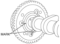
- (1) Mark the camshaft and variable valve timing actuator as shown in the figure to make sure they are installed in their original position.
-
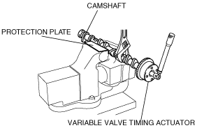
- (2) Secure the camshaft in a vise.
-
- (3) Loosen the variable valve timing actuator tightening bolt.
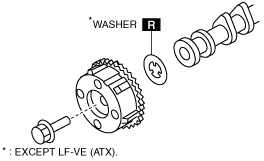
3. Install a new washer. (Except LF-VE (ATX).)
-
Note
-
• The washers do not have to be installed on the LF-VE (ATX) (there is no problem with installing them).
• Be careful not to install a washer on only the IN or EX side.
-
― If the washers are not installed, do not install the washers to both the IN and EX sides.
― If the washers are to be installed, install them on both the IN and EX sides.
4. Install the variable valve timing actuator.
-
Caution
-
• When the variable valve timing actuator is replaced with a new one, mark it in the same location as the old one.
- (1) Secure the camshaft in a vise.
- (2) Align the marks of the camshaft and variable valve timing actuator.
- (3) Tighten variable valve timing actuator tightening bolt.
-
-
Tightening torque
-
69—75 N·m {7.1—7.6 kgf·m, 51—55 ft·lbf}
5. Follow the valve clearance adjustment procedure from 26 to 56 and install the intake camshaft and variable valve timing actuator. (See VALVE CLEARANCE ADJUSTMENT [L8, LF, L5].)