|
am6zzw00001789
OIL CONTROL VALVE (OCV) INSPECTION [LF, L5]
id0110a7801400
Coil Resistance Inspection
1. Disconnect the negative battery cable.
2. Remove the plug hole plate. (See PLUG HOLE PLATE REMOVAL/INSTALLATION [L8, LF, L5].)
3. Disconnect the OCV connector.
4. Measure the resistance between terminals A and B using an ohmmeter.
am6zzw00001789
|
5. Connect the OCV connector.
6. Install the plug hole plate. (See PLUG HOLE PLATE REMOVAL/INSTALLATION [L8, LF, L5].)
7. Connect the negative battery cable.
Spool Valve Operation Inspection
1. Remove the OCV. (See OIL CONTROL VALVE (OCV) REMOVAL/INSTALLATION [LF, L5].)
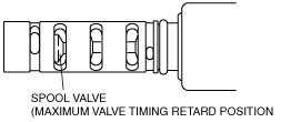
2. Verify that the spool valve in the OCV is in the maximum valve timing retard position as indicated in the figure.
b3e0110e090
|
3. Verify that the battery is fully charged. (See BATTERY INSPECTION [L8, LF, L5].)
am6zzw00001789
|
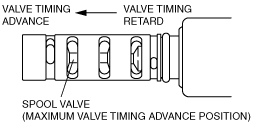
4. Apply battery positive voltage between the OCV terminals and verify that the spool valve operates and moves to the maximum valve timing advance position.
b3e0110e091
|
5. Stop applying battery positive voltage and verify that the spool valve returns to the maximum valve timing retard position.
1. Install the OCV. (See OIL CONTROL VALVE (OCV) REMOVAL/INSTALLATION [LF, L5].)