BALANCER UNIT CONSTRUCTION/OPERATION [MZR-CD 2.2]
id0110f2101700
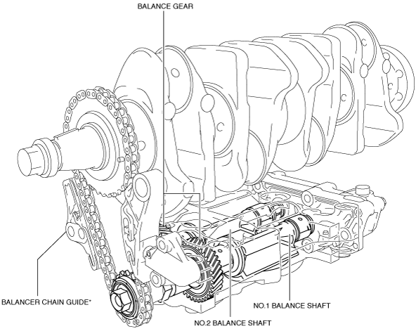
Construction
• The balancer unit consists of two balancer shafts (No.1 and No.2) with weights, the balancer unit case.
• The two balancer shafts (No.1 and No.2) are driven by the chain which is attached to the crankshaft.
• The balancer unit cannot be disassembled because it is a precision unit.
* :Depending on the vehicle's period of manufacture, it is either equipped or not equipped with a balancer chain guide. The vehicle's marketability and reliability are sufficiently satisfied even if a balancer chain guide is not equipped.
Operation
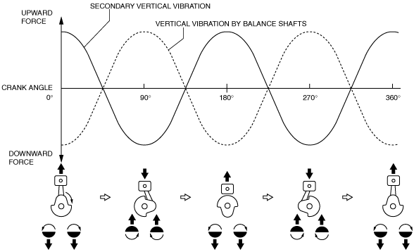
• In-line four-cylinder engines are normally constructed to have the pistons of the No.1 and No.4 cylinders moving in the opposite direction of those of the inner No.2 and No.3 cylinders. Therefore, the force generated by pistons No.1 and No.4 offsets the force generated by pistons No.2 and No.3.
• Due to the inertial weight of the piston/rod components, however, different upward and downward forces are generated.
• Upward force is generated when the pistons are at TDC and BDC, and downward force is generated when the pistons are at the 90° and 270° crank angle position, which results in four vertical forces (two upward and two downward) for each combustion cycle. This is known as secondary vertical vibration and can be quite severe at high engine speeds.
• The balance shafts offset this secondary vertical vibration by creating vibration of the same magnitude (as indicated by the dotted line) in the opposite direction.