VALVE CLEARANCE ADJUSTMENT [MZR-CD 2.2]


id0110f2803300

1.  Complete the “BEFORE SERVICE PRECAUTION”. (See BEFORE SERVICE PRECAUTION [MZR-CD 2.2].)

2.  Disconnect the negative battery cable. (See BATTERY REMOVAL/INSTALLATION [MZR-CD 2.2].)

3.  Remove the engine cover. (See ENGINE COVER REMOVAL/INSTALLATION [MZR-CD 2.2].)

4.  Disconnect the ventilation hose.

5.  Disconnect the following parts and set the fuel injector wiring harness out of the way.

•  Fuel injector connector
•  Boost sensor connector
•  Fuel pressure sensor connector
•  EGR cooler bypass valve control solenoid valve connector
•  Front harness-short cord connector
am6zzw00004443

6.  Remove the fuel injectors. (See FUEL INJECTOR REMOVAL/INSTALLATION [MZR-CD 2.2].)

7.  Remove the insulator and cylinder head cover. (See TIMING CHAIN REMOVAL/INSTALLATION [MZR-CD 2.2].)

8.  Set the front mudguard (RH) out of the way. (See FRONT MUDGUARD REMOVAL/INSTALLATION.)

9.  Remove the splash shield (RH).

10.  Remove the crankshaft pulley cover.

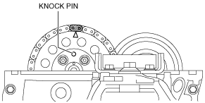
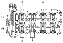
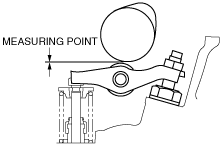
11.  Adjust the valve clearance using the following procedure.

Caution
•  Apply engine oil to the cam after measuring the valve clearance.
(1)  Rotate the crankshaft clockwise and align the knock pin to the position shown in the figure. In this position, the No.1 cylinder is at the TDC of the compression stroke.
am6zzw00004179
(2)  Adjust the valve clearance at A in the figure.
am6zzw00004282
1)  Loosen the locknut using the SST, and then loosen the adjusting screw using the hexagon wrench.
am6zzw00004190
2)  Insert a feeler gauge between the cam and rocker arm.
am6zzw00004189
Standard valve clearance [Engine cold]
IN : 0.07—0.17 mm {0.003—0.006 in}
EX : 0.12—0.22 mm {0.0048—0.0086 in}
3)  Adjust the valve clearance by turning the adjusting screw using the hexagon wrench.
4)  Tighten the locknut using the SST to specified torque.
Tightening torque
16—20 N·m {1.7—2.0 kgf·m, 12—14 ft·lbf}
5)  Verify the valve clearance.
Standard valve clearance [Engine cold]
IN : 0.07—0.17 mm {0.003—0.006 in}
EX : 0.12—0.22 mm {0.0048—0.0086 in}
(3)  Turn the crankshaft 360° clockwise and adjust the remaining valve clearance.

12.  Install in the reverse order of removal.

13.  Complete the “AFTER SERVICE PRECAUTION”. (See AFTER SERVICE PRECAUTION [MZR-CD 2.2].)