 |
am6zzw00000804
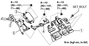
PCM REMOVAL/INSTALLATION [L8, LF, L5]
id014046802400
R.H.D.
1. Disconnect the negative battery cable.
2. Perform the following procedures.
3. Remove in the order indicated in the table.
4. When replacing the PCM on the vehicles, perform the following:
5. Install in the reverse order of removal.
U.K. specs.
am6zzw00000804
|
|
1
|
PCM cover
(See Set Bolt Removal Note.)
(See Set Bolt Installation Note.)
|
|
2
|
PCM connector
|
|
3
|
PCM
|
|
4
|
PCM bracket No.1
|
|
5
|
PCM bracket No.2
|
Except for U.K. specs.
am6zzw00003664
|
|
1
|
PCM cover
|
|
2
|
PCM connector
|
|
3
|
PCM
|
|
4
|
PCM bracket No.1
|
|
5
|
PCM bracket No.2
|
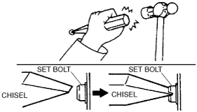
Set Bolt Removal Note
1. Using a chisel and a hammer, cut a groove on the head of the set bolt so that a screwdriver can be inserted.
2. Loose the set bolt using an impact screwdriver or pliers.
am6zzw00000120
|
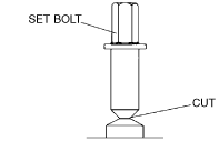
Set Bolt Installation Note
1. Install a new set bolt and tighten it until the neck of the bolt is cut.
am6zzw00000121
|
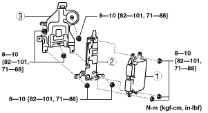
L.H.D.
1. Disconnect the negative battery cable.
2. Remove the junction member. (MTX)
3. Remove in the order indicated in the table.
4. Install in the reverse order of removal.
am6zzw00000805
|
|
1
|
PCM
(See PCM Removal Note.)
|
|
2
|
PCM bracket No.1
|
|
3
|
PCM bracket No.2
|
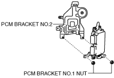
PCM Removal Note
1. Remove the PCM bracket No.1 nuts.
am6zzw00002919
|
2. Disconnect the PCM connector.
3. Remove the PCM.