 |
am6zzw00011627
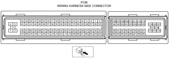
PCM INSPECTION [MZR-CD (RF Turbo)]
id0140f1802500
Without Using the M-MDS
am6zzw00011627
|
|
Terminal |
Signal |
Connected to |
Test condition |
Voltage (V) |
Inspection item |
|
|---|---|---|---|---|---|---|
|
1
|
Ground
|
Body ground
|
Under any condition
|
Below 1.0
|
• Related wiring harness
|
|
|
2
|
Ground
|
Body ground
|
Under any condition
|
Below 1.0
|
• Related wiring harness
|
|
|
3
|
Ground
|
Body ground
|
Under any condition
|
Below 1.0
|
• Related wiring harness
|
|
|
4
|
Common
|
Fuel injector
(No.1, No.2, No.3, No.4)
|
Inspect using the wave Profile.
|
Below 1.0
|
• Related wiring harness
• Fuel injector (No.1, No.2, No.3, No.4)
|
|
|
5
|
—
|
—
|
—
|
—
|
—
|
|
|
6
|
VBC solenoid valve
|
VBC solenoid valve
|
Inspect using the wave Profile.
|
• Related wiring harness
• VBC solenoid valve
|
||
|
7
|
EGR valve (EGR-)
|
EGR valve
|
Idle
|
Below 1.0
|
• Related wiring harness
• EGR valve
|
|
|
8
|
EGR valve (EGR+)
|
EGR valve
|
Inspect using the wave Profile.
|
• Related wiring harness
• EGR valve
|
||
|
9
|
Generator field coil control
|
Generator
|
Inspect using the wave Profile.
|
• Related wiring harness
• Generator
|
||
|
10
|
Suction control valve
|
Suction control valve
|
Inspect using the wave Profile.
|
• Related wiring harness
• Suction control valve
|
||
|
11
|
—
|
—
|
—
|
—
|
—
|
|
|
12
|
Sedimentor
|
Sedimentor switch
|
Sedimentor switch ON
|
Below 1.0
|
• Related wiring harness
• Sedimentor switch
|
|
|
Sedimentor switch OFF
|
B+
|
|||||
|
13
|
—
|
—
|
—
|
—
|
—
|
|
|
14
|
—
|
—
|
—
|
—
|
—
|
|
|
15
|
—
|
—
|
—
|
—
|
—
|
|
|
16
|
—
|
—
|
—
|
—
|
—
|
|
|
17
|
—
|
—
|
—
|
—
|
—
|
|
|
18
|
—
|
—
|
—
|
—
|
—
|
|
|
19
|
—
|
—
|
—
|
—
|
—
|
|
|
20
|
—
|
—
|
—
|
—
|
—
|
|
|
21
|
Fuel injector (#2)
|
Fuel injector No.2
|
Inspect using the wave Profile.
|
• Related wiring harness
• Fuel injector No.2
|
||
|
22
|
—
|
—
|
—
|
—
|
—
|
|
|
23
|
Fuel injector (#3)
|
Fuel injector No.3
|
Inspect using the wave Profile.
|
• Related wiring harness
• Fuel injector No.3
|
||
|
24
|
—
|
—
|
—
|
—
|
—
|
|
|
25
|
—
|
—
|
—
|
—
|
—
|
|
|
26
|
A/C
|
A/C relay
|
A/C operating
|
Below 1.0
|
• Related wiring harness
• A/C relay
|
|
|
A/C not operating
|
B+
|
|||||
|
27
|
Cooling fan control
|
Cooling fan relay No.1
|
Cooling fan No.1 operating
|
Below 1.0
|
• Related wiring harness
• Cooling fan relay No.1
|
|
|
Cooling fan No.1 not operating
|
B+
|
|||||
|
28
|
Cooling fan control
|
Cooling fan relay No.2
|
Cooling fan No.2 operating
|
Below 1.0
|
• Related wiring harness
• Cooling fan relay No.2
|
|
|
Cooling fan No.2 not operating
|
B+
|
|||||
|
29
|
Suction control valve
|
Suction control valve
|
Under any condition
|
Below 1.0
|
• Related wiring harness
• Suction control valve
|
|
|
30
|
—
|
—
|
—
|
—
|
—
|
|
|
31
|
—
|
—
|
—
|
—
|
—
|
|
|
32
|
High pressure
|
Refrigerant pressure switch (high)
|
Switch the ignition to ON
|
Below 1.0
|
• Related wiring harness
|
|
|
33
|
Exhaust gas temp (Lower)
|
Exhaust gas temperature sensor (Lower)
|
Exhaust gas temperature 50 °C {122 °F}
|
Approx. 5
|
• Related wiring harness
• Exhaust gas temp sensor (Lower)
|
|
|
34
|
A/F sensor heater control
|
A/F sensor heater
|
Inspect using the wave Profile.
|
• Related wiring harness
• A/F sensor heater
|
||
|
35
|
Ground
|
Body ground
|
Under any condition
|
Below 1.0
|
• Related wiring harness
|
|
|
36
|
—
|
—
|
—
|
—
|
—
|
|
|
37
|
Glow
|
Glow plug relay
|
15 s from when switch the ignition to ON position with ECT at 20 °C {68 °F} or less
|
B+
|
• Related wiring harness
• Glow plug relay
|
|
|
Idle
|
Below 1.0
|
|||||
|
38
|
—
|
—
|
—
|
—
|
—
|
|
|
39
|
Starter
|
Ignition switch, Starter relay
|
Cranking
|
Below 1.0
|
• Related wiring harness
|
|
|
40
|
Fuel injection (#4)
|
Fuel injector No.4
|
Inspect using the wave Profile.
|
• Related wiring harness
• Fuel injector No.4
|
||
|
41
|
—
|
—
|
—
|
—
|
—
|
|
|
42
|
Fuel injection (#1)
|
Fuel injector No.1
|
Inspect using the wave Profile.
|
• Related wiring harness
• Fuel injector No.1
|
||
|
43
|
—
|
—
|
—
|
—
|
—
|
|
|
44
|
Constant voltage (Vref)
|
Fuel pressure sensor
|
Switch the ignition to ON
|
Approx. 5
|
• Related wiring harness
• Fuel pressure sensor
|
|
|
45
|
Constant voltage (Vref)
|
EGR valve, Intake shutter valve, CKP sensor
|
Switch the ignition to ON
|
Approx. 5
|
• Related wiring harness
• EGR valve
• Intake shutter valve
• CKP sensor
|
|
|
46
|
CKP (NE+)
|
CKP sensor
|
Inspect using the wave Profile.
|
• Related wiring harness
• CKP sensor
|
||
|
47
|
CMP (G+)
|
CMP sensor
|
Inspect using the wave Profile.
|
• Related wiring harness
• CMP sensor
|
||
|
48
|
Fuel pressure
|
Fuel pressure sensor
|
Switch the ignition to ON
|
Approx. 1.0
|
• Related wiring harness
• Fuel pressure sensor
|
|
|
Engine speed is 3,000 rpm
|
Approx. 2.0
|
|||||
|
49
|
—
|
—
|
—
|
—
|
—
|
|
|
50
|
Fuel temp
|
Fuel temperature sensor
|
Switch the ignition to ON
|
Fuel temperature
40 °C {104 °F}
|
Approx. 1.6
|
• Related wiring harness
• Fuel temperature sensor
|
|
Fuel temperature
45 °C {113 °F}
|
Approx. 1.3
|
|||||
|
51
|
ECT
|
ECT sensor
|
Switch the ignition to ON
|
ECT 30 °C
{86 °F}
|
Approx. 2.61
|
• Related wiring harness
• ECT sensor
|
|
ECT 50 °C
{122 °F}
|
Approx. 1.72
|
|||||
|
ECT 60 °C
{140 °F}
|
Approx. 1.41
|
|||||
|
ECT 80 °C
{176 °F}
|
Approx. 0.88
|
|||||
|
52
|
MAP
|
Boost sensor
|
Switch the ignition to ON
|
Approx. 1.0
|
• Related wiring harness
• Boost sensor
|
|
|
Idle
|
Approx. 0.6
|
|||||
|
53
|
EGR position
|
EGR valve
|
Switch the ignition to ON
|
Below 1.0
|
• Related wiring harness
• EGR valve
|
|
|
EGR valve opening angle 36.5%
|
Approx. 2
|
|||||
|
54
|
MAF
|
MAF/IAT sensor
|
Switch the ignition to ON
|
Approx. 0.8
|
• Related wiring harness
• Exhaust gas temp sensor (Lower)
|
|
|
Idle
|
Approx. 1.6
|
|||||
|
55
|
IAT
|
MAF/IAT sensor
|
Switch the ignition to ON
|
IAT 30 °C
{86 °F}
|
Approx. 1.9
|
• Related wiring harness
• MAF/IAT sensor
|
|
IAT 40 °C
{104 °F}
|
Approx. 1.47
|
|||||
|
56
|
Exhaust gas temp (Upper)
|
Exhaust gas temperature sensor (Upper)
|
Exhaust gas temperature 50 °C {122 °F}
|
Approx. 5
|
• Related wiring harness
• Exhaust gas temperature sensor (Upper)
|
|
|
57
|
Exhaust gas temp (Middle)
|
Exhaust gas temperature sensor (Middle)
|
Exhaust gas temperature 50 °C {122 °F}
|
Approx. 5
|
• Related wiring harness
• Exhaust gas temperature sensor (Middle)
|
|
|
58
|
Press correction temp
|
Exhaust gas pressure correction temperature sensor
|
Switch the ignition to ON
|
Near temperature of sensor 20 °C {68 °F}
|
Approx. 2.3
|
• Related wiring harness
• Exhaust gas pressure correction temperature sensor
|
|
Near temperature of sensor 80 °C {176 °F}
|
Approx. 0.5
|
|||||
|
59
|
Constant voltage (Vref)
|
Boost sensor
|
Switch the ignition to ON
|
Approx. 5
|
• Related wiring harness
• Boost sensor
|
|
|
60
|
Constant voltage (Vref)
|
Exhaust gas pressure sensor
|
Switch the ignition to ON
|
Approx. 5
|
• Related wiring harness
• Exhaust gas pressure sensor
|
|
|
61
|
Ground
|
Exhaust gas temperature sensor (Upper, Middle)
|
Under any condition
|
Below 1.0
|
• Related wiring harness
• Exhaust gas temp sensor (upper, middle)
|
|
|
62
|
Ground
|
Exhaust gas pressure sensor
|
Under any condition
|
Below 1.0
|
• Related wiring harness
• Exhaust gas pressure sensor
|
|
|
63
|
Constant voltage (Vref)
|
APP sensor
|
Switch the ignition to ON
|
Approx. 5
|
• Related wiring harness
• APP sensor
|
|
|
64
|
Constant voltage (Vref)
|
CMP sensor
|
Switch the ignition to ON
|
Approx. 5
|
• Related wiring harness
• CMP sensor
|
|
|
65
|
CKP (NE-)
|
CKP sensor
|
Idle
|
Below 1.0
|
• Related wiring harness
• CKP sensor
|
|
|
66
|
CMP (G-)
|
CMP sensor
|
Idle
|
Below 1.0
|
• Related wiring harness
• CMP sensor
|
|
|
67
|
—
|
—
|
—
|
—
|
—
|
|
|
68
|
Ground
|
Exhaust gas pressure correction temperature sensor
|
Under any condition
|
Below 1.0
|
• Related wiring harness
• Exhaust gas pressure correction temperature sensor
|
|
|
69
|
Ground
|
Fuel pressure sensor
|
Under any condition
|
Below 1.0
|
• Related wiring harness
• Fuel pressure sensor
|
|
|
70
|
Ground
|
ECT sensor, Fuel temperature sensor, Intake shutter valve, EGR valve
|
Under any condition
|
Below 1.0
|
• Related wiring harness
• ECT sensor
• Fuel temperature sensor
• Intake shutter valve
• EGR valve
|
|
|
71
|
Ground
|
Boost sensor
|
Under any condition
|
Below 1.0
|
• Related wiring harness
• Boost sensor
|
|
|
72
|
Ground
|
Exhaust gas temperature sensor (lower)
|
Under any condition
|
Below 1.0
|
• Related wiring harness
• Exhaust gas temperature sensor (lower)
|
|
|
73
|
Ground
|
MAF/IAT sensor
|
Under any condition
|
Below 1.0
|
• Related wiring harness
• MAF/IAT sensor
|
|
|
74
|
Ground
|
IAT sensor No.2
|
Under any condition
|
Below 1.0
|
• Related wiring harness
• IAT sensor No.2
|
|
|
75
|
Glow
|
Glow plug
|
15s from 20 °C {68 °F} or less in water temperature and Switch the ignition to ON
|
B+
|
• Related wiring harness
• Glow plug
• Glow plug relay
|
|
|
Engine running after warm up
|
Below 1.0
|
|||||
|
76
|
—
|
—
|
—
|
—
|
—
|
|
|
77
|
Generator output voltage
|
Generator
|
Inspect using the wave Profile.
|
• Related wiring harness
|
||
|
78
|
Ground
|
MAF/IAT sensor
|
Under any condition
|
Below 1.0
|
• Related wiring harness
• MAF/IAT sensor
|
|
|
79
|
IAT
|
IAT sensor No.2
|
Switch the ignition to ON
|
IAT 30 °C
{86 °F}
|
Approx. 1.9
|
• Related wiring harness
• IAT sensor No.2
|
|
IAT 40 °C
{104 °F}
|
Approx. 1.47
|
|||||
|
80
|
—
|
—
|
—
|
—
|
—
|
|
|
81
|
Exhaust gas pressure
|
Exhaust gas pressure sensor
|
Switch the ignition to ON
|
Approx. 1.0
|
• Related wiring harness
• Exhaust gas pressure sensor
|
|
|
Idle
|
Approx. 1.2
|
|||||
|
82
|
Constant voltage (Vref)
|
APP sensor
|
Switch the ignition to ON
|
Approx. 5
|
• Related wiring harness
• APP sensor
|
|
|
83
|
APP
|
APP sensor
|
Accelerator pedal released
|
Approx. 1.04
|
• Related wiring harness
• APP sensor
|
|
|
Accelerator pedal depressed
|
Approx. 3.35
|
|||||
|
84
|
Ground
|
APP sensor
|
Under any condition
|
Below 1.0
|
• Related wiring harness
• APP sensor
|
|
|
85
|
A/F sensor
|
A/F sensor
|
Idle
|
Approx. 2.1
|
• Related wiring harness
• A/F sensor
|
|
|
86
|
Intake shutter valve position
|
Intake shutter valve
|
Idle
|
Clutch pedal released
|
Approx. 0.75
|
• Related wiring harness
• Intake shutter valve
|
|
Clutch pedal depressed
|
Approx. 3.9
|
|||||
|
87
|
CAN (L)
|
Instrument cluster, ABS HU/CM, DSC HU/CM
|
Because this terminal is for CAN, good/no good judgment by terminal voltage is not possible
|
• Related wiring harness
|
||
|
88
|
—
|
—
|
—
|
—
|
—
|
|
|
89
|
—
|
—
|
—
|
—
|
—
|
|
|
90
|
—
|
—
|
—
|
—
|
—
|
|
|
91
|
APP
|
APP sensor
|
Accelerator pedal released
|
Approx. 1.58
|
• Related wiring harness
• APP sensor
|
|
|
Accelerator pedal depressed
|
Approx. 3.89
|
|||||
|
92
|
Ground
|
APP sensor
|
Under any condition
|
Below 1.0
|
• Related wiring harness
• APP sensor
|
|
|
93
|
A/F sensor
|
A/F sensor
|
Idle
|
0↔1
|
• Related wiring harness
• A/F sensor
|
|
|
94
|
—
|
—
|
—
|
—
|
—
|
|
|
95
|
CAN (H)
|
Instrument cluster, ABS HU/CM, DSC HU/CM
|
Because this terminal is for CAN, good/no good judgment by terminal voltage is not possible
|
• Related wiring harness
|
||
|
96
|
—
|
—
|
—
|
—
|
—
|
|
|
97
|
—
|
—
|
—
|
—
|
—
|
|
|
98
|
—
|
—
|
—
|
—
|
—
|
|
|
99
|
Starter
|
Ignition switch, Starter relay
|
Switch the ignition to ON (START) position
|
B+
|
• Related wiring harness
• Ignition switch
• Main fuse
|
|
|
Except for Switch the ignition to ON (START) position
|
Below 1.0
|
|||||
|
100
|
Brake
|
Brake switch
|
Brake pedal depressed
|
Below 1.0
|
• Related wiring harness
• Brake switch
|
|
|
Brake pedal released
|
B+
|
|||||
|
101
|
Brake
|
Brake switch 2
|
Brake pedal depressed
|
B+
|
• Related wiring harness
• Brake switch
|
|
|
Brake pedal released
|
Below 1.0
|
|||||
|
102
|
Auto cruise
|
Auto cruise switch
|
Cruise main SW ON
|
Approx. 0
|
• Related wiring harness
• Auto cruise switch
|
|
|
Cancel SW ON
|
Approx. 1.8
|
|||||
|
Set/ Cost SW ON
|
Approx. 3.8
|
|||||
|
Res/ Acc SW ON
|
Approx. 4.6
|
|||||
|
Other
|
Approx. 5.0
|
|||||
|
103
|
Ground
|
Auto cruise switch
|
Under any condition
|
Below 1.0
|
• Related wiring harness
• Auto cruise switch
|
|
|
104
|
—
|
—
|
—
|
—
|
—
|
|
|
105
|
Main relay control
|
Main relay
|
Switch the ignition to ON
|
Below 1.0
|
• Related wiring harness
• Main relay
|
|
|
Switch the ignition to OFF
|
B+
|
|||||
|
106
|
—
|
—
|
—
|
—
|
—
|
|
|
107
|
IG 1
|
Ignition switch
|
Switch the ignition to ON and Start position
|
B+
|
• Related wiring harness
|
|
|
Switch the ignition to other position
|
Below 1.0
|
|||||
|
108
|
—
|
—
|
—
|
—
|
—
|
|
|
109
|
Clutch
|
Clutch switch
|
Clutch pedal depressed
|
Below 1.0
|
• Related wiring harness
• Clutch switch
|
|
|
Clutch pedal released
|
B+
|
|||||
|
110
|
Neutral
|
Neutral switch
|
Neutral
|
Below 1.0
|
• Related wiring harness
• Neutral switch
|
|
|
Other
|
B+
|
|||||
|
111
|
—
|
—
|
—
|
—
|
—
|
|
|
112
|
—
|
—
|
—
|
—
|
—
|
|
|
113
|
—
|
—
|
—
|
—
|
—
|
|
|
114
|
Ground
|
Body ground
|
Under any condition
|
Below 1.0
|
• Related wiring harness
|
|
|
115
|
—
|
—
|
—
|
—
|
—
|
|
|
116
|
Intake shutter valve (ISV+)
|
Intake shutter valve
|
Idle
|
0 ÛB+
|
• Related wiring harness
• Intake shutter valve
|
|
|
117
|
Ground
|
Body ground
|
Under any condition
|
Below 1.0
|
• Related wiring harness
|
|
|
118
|
Intake shutter valve (ISV-)
|
Intake shutter valve
|
Idle
|
0 ÛB+
|
• Related wiring harness
• Intake shutter valve
|
|
|
119
|
B+
|
Main relay
|
Main relay ON
|
B+
|
• Related wiring harness
• Main relay
|
|
|
Main relay OFF
|
Below 1.0
|
|||||
|
120
|
B+
|
Main relay
|
Main relay ON
|
B+
|
• Related wiring harness
• Main relay
|
|
|
Main relay OFF
|
Below 1.0
|
|||||
|
121
|
Power supply
|
Power supply
|
Under any condition
|
B+
|
• Related wiring harness
|
|
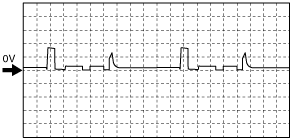
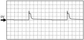
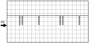
Inspection Using An Oscilloscope (Reference)
Common signal
am6zzw00011628
|
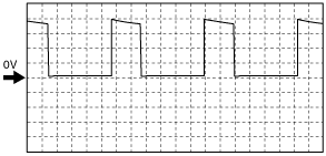
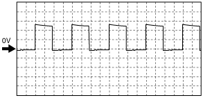
VBC solenoid valve signal
am6zzw00011629
|
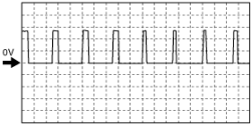
EGR valve (EGR+) signal
am6zzw00011630
|
Generator field coil control signal
am6zzw00011631
|
Suction control valve signal
am6zzw00011632
|
Fuel injection signal
am6zzw00011633
|
A/F sensor heater control signal
am6zzw00011634
|
CKP (NE+) signal
am6zzw00011635
|
CMP (G+) signal
am6zzw00011636
|
Generator signal
am6zzw00011637
|
Using M-MDS
1. Connect the M-MDS to the DLC-2. (See ON-BOARD DIAGNOSTIC TEST [MZR-CD (RF Turbo)].)
am6zzw00011638
|
2. Measure the PID value.
3. Switch the ignition to ON.
PID Monitor Table
|
Monitor item (Definition) |
Unit/Condition |
Condition/Specification (Reference) |
Inspection item |
PCM terminal |
||||||
|---|---|---|---|---|---|---|---|---|---|---|
|
AC_REQ
(A/C switch)
|
OFF/ON
|
Refrigerant pressure switch is off: Off
Others: On
|
A/C switch
|
32
|
||||||
|
ACCS
(Air conditioning compressor cycling switch)
|
OFF/ON
|
A/C switch ON and fan switch ON: On
Others: Off
|
Inspect following PIDs: AC_REQ, APP1, APP2, ECT, RPM
|
26
|
||||||
|
ALTF
(Generator field coil control duty signal)
|
%
|
Switch the ignition to ON: 0%
Idle: 0—100%
|
Inspect following PIDs:
IAT, ECT, RPM, VPWR, ALTT V
|
9
|
||||||
|
ALTT V
(Generator output voltage)
|
V
|
Switch the ignition to ON: 0 V
Idle: Approx. 10 V
|
Generator
|
77
|
||||||
|
APP
(Accelerator pedal position)
|
%
|
Accelerator pedal released: 0%
Accelerator pedal depressed: 100%
|
Inspect following PIDs:
APP1, APP2
|
83, 91
|
||||||
|
APP1
(Accelerator pedal position sensor 1)
|
%
|
Accelerator pedal released: 0%
Accelerator pedal depressed: 100%
|
APP sensor
|
83
|
||||||
|
V
|
Accelerator pedal released:
Approx. 1.04 V
Accelerator pedal depressed:
Approx. 3.35 V
|
|||||||||
|
APP2
(Accelerator pedal position sensor 2)
|
%
|
Accelerator pedal released: 0%
Accelerator pedal depressed: 100%
|
APP sensor
|
91
|
||||||
|
V
|
Accelerator pedal released:
Approx. 1.58 V
Accelerator pedal depressed:
Approx. 3.89 V
|
|||||||||
|
ARPMDES
(Target engine speed)
|
RPM
|
No load: 725—825 rpm
E/L operating: 725—825 rpm
P/S operating: 725—825 rpm
A/C ON: 700—800 rpm
|
Inspect following PIDs:
IVS, AC_REQ, IAT, ECT, BOOST_DSD, FRP, RPM, VSS
|
—
|
||||||
|
BARO
(Barometric pressure)
|
Pa
|
Indicate Barometric pressure.
|
BARO sensor
|
—
|
||||||
|
V
|
BARO 101.3 kPa: Approx. 3.6V
|
|||||||||
|
BAT
(Intake Air Temperature)
|
°C
|
Intake air temperature is display
|
IAT sensor No.2
|
79
|
||||||
|
BAT_V
(Intake Air Temperature sensor No.2)
|
V
|
30°C {86 °F}: Approx. 1.9 V
40°C {104 °F}: Approx. 1.47 V
|
||||||||
|
BOO
(Brake ON/OFF)
|
OFF/ON
|
Brake pedal released: Off
Brake pedal depressed: On
|
Brake switch
|
100
|
||||||
|
BOOST_DSD (Desired boost pressure)
|
Pa
|
Desired boost pressure is displayed.
|
Perform applicable DTC troubleshooting.
|
—
|
||||||
|
CHRGLP
(Generator warning light)
|
OFF/ON
|
Switch the ignition to ON: On
Idle: Off
|
Perform applicable DTC troubleshooting.
|
—
|
||||||
|
CPP
|
OFF/ON
|
Clutch pedal released: Off
Clutch pedal depressed: On
|
Clutch switch
|
109
|
||||||
|
DPF_LMP_CNT
|
—
|
Displays the number of diesel particulate filter indicator light illuminations.
|
—
|
—
|
||||||
|
DPF_REG_CNT
|
—
|
Displays the number of diesel particulate filter regenerations.
|
—
|
—
|
||||||
|
DSC_ACT
(DSC control enable/disable)
|
OFF/ON
|
Switch the ignition to ON: Off
|
—
|
—
|
||||||
|
Idle: On
|
||||||||||
|
ECT
(Engine coolant temperature)
|
°C
|
Engine coolant temperature is displayed.
|
ECT sensor.
|
51
|
||||||
|
V
|
ECT 30 °C {86 °F}: Approx. 2.61 V
ECT 50 °C {122 °F}: Approx. 1.72 V
ECT 60 °C {140 °F}: Approx. 1.41 V
ECT 80 °C {176 °F}: Approx. 0.88 V
|
|||||||||
|
EGR_LRN
(EGR valve)
|
—
|
Displays EGR valve fully-closed learning value.
|
EGR valve
|
53
|
||||||
|
EGRP
(EGR valve)
|
V
|
EGR valve opening angle 36.5%: Approx. 2 V
|
EGR valve
|
|||||||
|
mm
|
EGR valve opening angle 40%:
Approx. 4 mm
|
|||||||||
|
%
|
Displays EGR valve opening angle.
|
|||||||||
|
ENG_STAT
|
Cranking / Running / Stalled
|
Displays the engine conditions.
|
—
|
—
|
||||||
|
EQ_RAT11
(Equivalence Ratio (Lambda))
|
—
|
Idle: 1.99
|
Inspect following PIDs:
BAT, BAT_V, IAT, ECT, O2S11, O2S11_CAL, O2S11_MODE
|
85, 93
|
||||||
|
EXH_FL
|
—
|
Displays the exhaust gas flow amount.
|
—
|
|
||||||
|
EXHPRESS_DIF
(Exhaust gas pressure sensor)
|
Pa
|
Indicates the difference in exhaust gas pressure before and after passing the diesel particulate filter.
|
Exhaust pressure sensor
|
81
|
||||||
|
V
|
||||||||||
|
EXHTEMP1
(Exhaust gas temperature sensor)
|
V
|
Indicate the exhaust gas temperature.
|
Exhaust gas temperature sensor (upper)
|
56
|
||||||
|
°C
|
||||||||||
|
EXHTEMP2
(Exhaust gas temperature sensor)
|
V
|
Indicate the exhaust gas temperature.
|
Exhaust gas temperature sensor (middle)
|
57
|
||||||
|
°C
|
||||||||||
|
EXHTEMP3
(Exhaust gas temperature sensor)
|
V
|
Indicate the exhaust gas temperature.
|
Exhaust gas temperature sensor (lower)
|
33
|
||||||
|
°C
|
||||||||||
|
FAN1
(FAN1 Control Signal)
|
OFF/ON
|
Cooling fan relay No.1 opening: ON
Cooling fan relay No.1 not opening: OFF
|
Cooling fan relay No.1
|
27
|
||||||
|
FAN2
(FAN2 Control Signal)
|
OFF/ON
|
Cooling fan relay No.2 opening: ON
Cooling fan relay No.2 not opening: OFF
|
Coolong fan relay No.2
|
28
|
||||||
|
Fl_LRN_01
(Fuel injector No.1)
|
—
|
Fuel injection learning value (injector 1 at 35MPa)
|
Fuel injector No.1
|
42
|
||||||
|
Fl_LRN_02
(Fuel injector No.2)
|
—
|
Fuel injection learning value (injector 2 at 35MPa)
|
Fuel injector No.2
|
21
|
||||||
|
Fl_LRN_03
(Fuel injector No.3)
|
—
|
Fuel injection learning value (injector 3 at 35MPa)
|
Fuel injector No.3
|
23
|
||||||
|
Fl_LRN_04
(Fuel injector No.4)
|
—
|
Fuel injection learning value (injector 4 at 35MPa)
|
Fuel injector No.4
|
40
|
||||||
|
Fl_LRN_11
(Fuel injector No.1)
|
—
|
Fuel injection learning value (injector 1 at 65MPa)
|
Fuel injector No.1
|
42
|
||||||
|
Fl_LRN_12
(Fuel injector No.2)
|
—
|
Fuel injection learning value (injector 2 at 65MPa)
|
Fuel injector No.2
|
21
|
||||||
|
Fl_LRN_13
(Fuel injector No.3)
|
—
|
Fuel injection learning value (injector 3 at 65MPa)
|
Fuel injector No.3
|
23
|
||||||
|
Fl_LRN_14
(Fuel injector No.4)
|
—
|
Fuel injection learning value (injector 4 at 65MPa).
|
Fuel injector No.4
|
40
|
||||||
|
Fl_LRN_21
(Fuel injector No.1)
|
—
|
Fuel injection learning value (injector 1 at 100MPa)
|
Fuel injector No.1
|
42
|
||||||
|
Fl_LRN_22
(Fuel injector No.2)
|
—
|
Fuel injection learning value (injector 2 at 100MPa)
|
Fuel injector No.2
|
21
|
||||||
|
Fl_LRN_23
(Fuel injector No.3)
|
—
|
Fuel injection learning value (injector 3 at 100MPa)
|
Fuel injector No.3
|
23
|
||||||
|
Fl_LRN_24
(Fuel injector No.4)
|
—
|
Fuel injection learning value (injector 4 at 100MPa)
|
Fuel injector No.4
|
40
|
||||||
|
Fl_LRN_31
(Fuel injector No.1)
|
—
|
Fuel injection learning value (injector 1 at 140MPa)
|
Fuel injector No.1
|
42
|
||||||
|
Fl_LRN_32
(Fuel injector No.2)
|
—
|
Fuel injection learning value (injector 2 at 140MPa)
|
Fuel injector No.2
|
21
|
||||||
|
Fl_LRN_33
(Fuel injector No.3)
|
—
|
Fuel injection learning value (injector 3 at 140MPa)
|
Fuel injector No.3
|
23
|
||||||
|
Fl_LRN_34
(Fuel injector No.4)
|
—
|
Fuel injection learning value (injector 4 at 140MPa)
|
Fuel injector No.4
|
40
|
||||||
|
FIA_DSD
(Fuel injector)
|
—
|
Indicate the desired injector correction.
|
Fuel injector
|
—
|
||||||
|
FIP_FL
(Supply pump flow control)
|
A
|
Idle: Approx. 1.7 A
|
Inspect following PIDs:
AC_REQ, BAT, BAT_V, ECT, BOOST_DSD, FRP, IVS, IAT, RPM, VSS
|
—
|
||||||
|
FIP_FL_DSD
(Supply pump flow desired)
|
—
|
Switch the ignition to ON: Approx. 0 mm3/stroke
Idle: Approx. 55 mm3/stroke
|
Inspect following PIDs:
AC_REQ, BAT, BAT_V, ECT, BOOST_DSD, FRP, IVS, IAT, RPM, VSS
|
—
|
||||||
|
FIP_LRN
(Supply pump learning amount)
|
NOT_LRN / TMP_LRN / CMP_LRN
|
Indicate the supply pump learning amount.
|
Inspect following PIDs:
AC_REQ, BAT, BAT_V, ECT, BOOST_DSD, FRP, IVS, IAT, RPM, VSS
|
—
|
||||||
|
A
|
||||||||||
|
FIP_SCV
(Supply pump suction control valve)
|
A
|
Switch the ignition to ON: Approx. 0 mA
Idle: 1.67—1.73 A
|
Inspect following PIDs:
AC_REQ, BAT, BAT_V, ECT, BOOST_DSD, FRP, IVS, IAT, RPM, VSS
|
10, 29
|
||||||
|
FLT
(Fuel temperature)
|
°C
|
Fuel temperature is displayed.
|
Fuel temperature sensor
|
50
|
||||||
|
FP
(Fuel pump relay)
|
%
|
Idle: Approx. 45%
|
Inspect following PIDs: RPM
|
—
|
||||||
|
FRP
(Fuel pressure sensor)
|
V
|
Switch the ignition to ON: Approx. 1 V
|
Fuel pressure sensor
|
48
|
||||||
|
Idle: Approx. 1.54 V
2,000 rpm: Approx. 1.7 V
|
||||||||||
|
Pa
|
Switch the ignition to ON: 0 kPa {0 kgf/cm2, 0 psi}
|
|||||||||
|
Idle: Approx. 34 MPa {347 kgf/cm2, 4931 psi}
2,000 rpm: Approx. 43 MPa {438 kgf/cm2, 6237 psi}
|
||||||||||
|
FRP_DSD
|
Pa
|
Switch the ignition to ON: 0 kPa {0 kgf/cm2, 0 psi}
Idle: Approx. 34 MPa {347 kgf/cm2, 4931 psi}
|
||||||||
|
GENVDSD
(Generator voltage desired)
|
V
|
Indicate the generator voltage desired.
|
Perform applicable DTC troubleshooting.
|
—
|
||||||
|
GP_LMP
(Glow indicator light)
|
OFF/ON
|
Glow indicator light Off: Off
Glow indicator light ON: On
|
Inspect following PIDs:
ECT, BOOST_DSD, VSS
|
37
|
||||||
|
GPC
(Glow plug control)
|
OFF/ON
|
Switch the ignition to ON: Off
|
||||||||
|
Cranking: On
Idle: Off
|
||||||||||
|
HTR11
(A/F sensor heater control)
|
%
|
Switch the ignition to ON: 0%
|
Inspect following PIDs:
BAT, BAT_V, IAT, MAF, ECT, RPM
|
34
|
||||||
|
IAT
(Intake air temperature)
|
V
|
30°C {86 °F}: Approx. 1.9 V
40°C {104 °F}: Approx. 1.47 V
|
IAT sensor
|
55
|
||||||
|
°C
|
Intake air temperature is display
|
|||||||||
|
INGEAR
(in gear)
|
OFF/ON
|
When the following conditions are satisfied: On
• Not neutral
Except above: Off
|
Neutral switch
|
109
|
||||||
|
INJ_LRN_F1
|
—
|
Displays the cause of the fuel injection amount learning error.
|
—
|
—
|
||||||
|
INJ_LRN_F2
|
—
|
Displays the cause of the fuel injection amount learning error.
|
—
|
—
|
||||||
|
ISV_ACT
(Intake Shatter Valve Control Actual)
|
°
|
Switch the ignition to ON: Approx. 89°
Idle: 6.6°
|
Intake shutter valve
|
86
|
||||||
|
ISV_DSD
(Intake Shatter Valve Control Desired)
|
°
|
Switch the ignition to ON: Approx. 6.7°
Idle: Approx. 80°
|
Intake shutter valve
|
86
|
||||||
|
%
|
Switch the ignition to ON: Approx. 6.7%
Idle: Approx. 80%
|
|||||||||
|
ISV_LRN_C
(Intake Shatter Valve Learning Value - Closed)
|
°
|
Idle: Approx. -0.59 °
|
Intake shutter valve
|
86
|
||||||
|
ISV_POS
(Intake Shatter Valve Position)
|
V
|
Switch the ignition to ON: Approx. 4.1 V
Idle: Approx. 0.8 V
|
Intake shutter valve
|
86
|
||||||
|
%
|
Switch the ignition to ON: Approx. 88%
Idle: Approx. 5.8%
|
|||||||||
|
IVS
|
Idle / Off Idle
|
Idle: Idle
Except above: Off Idle
|
—
|
—
|
||||||
|
LOAD
(Engine load)
|
%
|
Switch the ignition to ON: 0%
Idle: Approx. 8.62%
|
—
|
—
|
||||||
|
MAF
(Mass Air Flow)
|
g/sec
|
Switch the ignition to ON: 0 g/s
Idle: Approx. 13 g/s
2,000 rpm: Approx. 21 g/s
|
MAF sensor
|
54
|
||||||
|
V
|
Switch the ignition to ON: Approx. 0.8 V
Idle: Approx. 1.6 V
2,000 rpm: Approx. 2.4 V
|
|||||||||
|
MAF_DSD
(Mass Air Flow Desired)
|
g/sec
|
Indicate the mass air flow desired.
|
MAF sensor
|
54
|
||||||
|
MAP
(Manifold absolute pressure sensor)
|
Pa
|
Manifold absolute pressure is displayed.
|
MAP sensor
|
52
|
||||||
|
V
|
Switch the ignition to ON: Approx. 1.0 V
Idle: Approx. 0.6 V
|
|||||||||
|
MIL
(Malfunction Indicator Lamp)
|
On/Off
|
Switch the ignition to ON: On
|
Perform applicable DTC troubleshooting.
|
—
|
||||||
|
Idle: Off
|
||||||||||
|
MIL_DIS
(The distance travelled since the %h(MIL) was activated.)
|
Km
|
Indicate the travelled distance since the MIL illuminated.
|
—
|
|||||||
|
O2
(A/F sensor)
|
%
|
Engine switch ON: Approx. 0%
|
A/F sensor
|
85, 93
|
||||||
|
O2S11
(A/F sensor (bank 1, sensor 1))
|
V
|
Switch the ignition to ON: Approx. 0 A
|
||||||||
|
A
|
||||||||||
|
O2S11_CAL
(A/F sensor)
|
—
|
Displays A/F sensor calibration value.
|
||||||||
|
O2S11_MODE
|
—
|
Displays the activation condition of the A/F sensor.
|
||||||||
|
OIL_DIL_CNT
|
—
|
Number of engine oil deteriorated events.
|
—
|
—
|
||||||
|
PM_ACC
(PM accumulation amount)
|
—
|
Displays PM accumulation amount.
|
—
|
—
|
||||||
|
PM_ACC_DSD
(PM accumulation amount desired)
|
—
|
Displays PM accumulation amount.
|
—
|
—
|
||||||
|
PM_GEN
(PM generation amount)
|
—
|
Displays PM generation amount.
|
—
|
—
|
||||||
|
REG_DIS
(Distance Since last DPF Regeneration)
|
Km
|
Displays the distance travelled after diesel particulate filter regeneration.
|
—
|
—
|
||||||
|
REG_FAIL_C
(DPF Regeneration Failure Condition)
|
TIMEOUT/VSS_DET/ECT_HIGH/ECT_LOW
|
Displays the cause of the diesel particulate filter regeneration error.
|
—
|
—
|
||||||
|
REG_REQ_A
(Automatic Regeneration Request)
|
OFF/ON
|
Displays ON during diesel particulate filter automatic regeneration.
|
—
|
—
|
||||||
|
REG_REQ_F
(Forced Regeneration Request)
|
OFF/ON
|
Displays ON during diesel particulate filter manual regeneration.
|
—
|
—
|
||||||
|
RPM
(Engine Revolutions Per Minute)
|
RPM
|
Switch the ignition to ON: 0 RPM
|
CKP sensor
|
46, 65
|
||||||
|
Idle
|
Clutch pedal released: 700—800 RPM
Clutch pedal depressed: 725—825 RPM
|
|||||||||
|
SC_CANCEL
(Cruise cancel switch)
|
Active/Inactive
|
Cruise cancel switch released: Inactive
Cruise cancel switch depressed: Active
|
Cruise control switch
|
102
|
||||||
|
SC_LMP
|
OFF/ON
|
Cruise indicator light ON: On
Cruise indicator light Off: Off
|
Cruise control switch
|
|||||||
|
SC_OFF
|
Active/Inactive
|
Cruise OFF switch released: Inactive
Cruise OFF switch depressed: Active
|
Cruise control switch
|
|||||||
|
SC_ON
(Cruise control switch)
|
Active/Inactive
|
Cruise main indicator light ON: On
Cruise main indicator light Off: Off
|
Cruise control switch
|
|||||||
|
SC_RES
(Cruise resume switch)
|
Active/Inactive
|
Cruise resume switch released: Inactive
Cruise resume switch depressed: Active
|
Cruise control switch
|
|||||||
|
SC_SET-
(Cruise control switch)
|
Active/Inactive
|
Cruise SET (-) switch released: Inactive
Cruise SET (-) switch depressed: Active
|
Cruise control switch
|
|||||||
|
SC_SET+
(Cruise control switch)
|
Active/Inactive
|
Cruise SET (+) switch released: Inactive
Cruise SET (+) switch depressed: Active
|
Cruise control switch
|
|||||||
|
SCCS
(Speed Control Command Switch)
|
V
|
Switch the ignition to ON: 5 V
|
Cruise control switch
|
|||||||
|
VBCV
(VBC solenoid valve control)
|
%
|
Switch the ignition to ON: 5.32%
Idle: Approx. 46%
2,000 rpm: Approx. 45%
|
Inspect following PIDs: IVS, MAF, ECT, RPM
Inspect VBC solenoid valve.
|
6
|
||||||
|
VPWR
(Module supply voltage)
|
V
|
Switch the ignition to ON: Approx. 12 V
|
Main relay
|
119, 120
|
||||||
|
VSS
(Vehicle speed)
|
KPH
|
Vehicle speed is displayed.
|
Perform applicable DTC troubleshooting.
|
—
|
||||||