Note
• Verify the wheel unit type of the vehicle before performing the removal/installation.The wheel unit has two types, type A and type B.Refer to the figure below to identify the wheel unit type.
amxuuw00002282
|
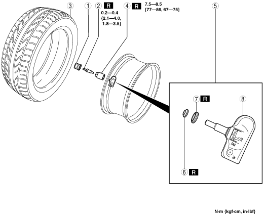
WHEEL UNIT REMOVAL/INSTALLATION
id021200800600
amxuuw00002282
|
Type A
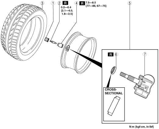
1. Remove in the order indicated in the table.
2. Install in the reverse order of removal.
3. Install the valve core and valve cap, put air into the tire.
4. When replacing wheel unit (s), register the new wheel unit ID (s). (See WHEEL UNIT ID REGISTRATION.)
am6xuw00003632
|
|
1
|
Valve cap
|
|
2
|
Valve core
(See Valve core removal note.)
|
|
3
|
Tire
|
|
4
|
Valve nut
|
|
5
|
Wheel unit component
|
|
6
|
Seal
|
|
7
|
Seal washer
|
|
8
|
Wheel unit
|
Valve core removal note
1. Remove the valve core of the wheel unit, and bleed the air from the tire.
Wheel unit component removal note
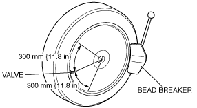
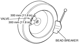
1. Set the bead breaker at the position laterally opposed to the valve.
am6xuw00003616
|
2. Break the bead loose.
3. Break the bead loose on the other side of the wheel.
am6xuw00003617
|
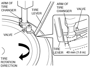
4. Insert the tire lever at the point 40 mm {1.6 in} from the wheel unit in the direction that the tire changer turntable rotates.
am6xuw00003618
|
5. Remove the bead from the wheel.
am6xuw00003619
|
6. For the other side, insert the tire lever at the point of 40 mm {1.6 in} from the wheel unit in the direction that the tire changer turntable rotates, and remove the bead from the wheel.
7. Remove the wheel unit.
Wheel unit component installation note
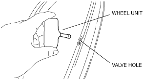
1. Insert the wheel unit valve into the valve hole so that the polyurethane foam side faces the rim.
am6xuw00002442
|
2. Install the nut from the outer side of the wheel.
3. Tighten the valve nut slowly (15 rpm max.) to 7.5—8.5 N·m {77—86 kgf·cm, 67—75 in·lbf} in one rotation.
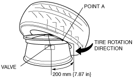
4. Set the tire at the point A (200 mm {7.87 in} away from the valve hole), and install the tire.
am6xuw00003620
|
5. Set the tire at the point A (200 mm {7.87 in} away from the valve hole).
am6xuw00003621
|
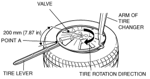
6. Install the tire.
Type B
1. Remove in the order indicated in the table.
2. Install in the reverse order of removal.
3. Install the valve core and valve cap, put air into the tire.
4. When replacing wheel unit (s), register the new wheel unit ID (s). (See WHEEL UNIT ID REGISTRATION.)
amxuuw00002283
|
|
1
|
Valve cap
|
|
2
|
Valve core
(See Valve core removal note.)
|
|
3
|
Tire
(See Tire removal note.)
(See Tire installation note.)
|
|
4
|
Valve nut
|
|
5
|
Wheel unit component
|
|
6
|
Seal
|
|
7
|
Wheel unit
|
Valve core removal note
1. Remove the valve core of the wheel unit, and bleed the air from the tire.
Tire removal note
1. Set the bead breaker at the position laterally opposed to the valve.
am6xuw00003616
|
2. Break the bead loose.
3. Break the bead loose on the other side of the wheel.
am6xuw00003617
|
4. Insert the tire lever at the point 40 mm {1.6 in} from the wheel unit in the direction that the tire changer turntable rotates.
am6xuw00003618
|
5. Remove the bead from the wheel.
am6xuw00003619
|
6. For the other side, insert the tire lever at the point of 40 mm {1.6 in} from the wheel unit in the direction that the tire changer turntable rotates, and remove the bead from the wheel.
Tire installation note
1. Set the tire at the point A (200 mm {7.87 in} away from the valve hole), and install the tire.
am6xuw00003620
|
2. Set the tire at the point A (200 mm {7.87 in} away from the valve hole).
am6xuw00003621
|
3. Install the tire.
Wheel unit component installation note
1. Insert the valve into the wheel unit in the order shown in the figure.
am6xuw00003643
|
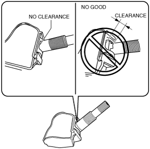
2. Verify that the valve is installed into the wheel unit completely as shown in the figure.
am6xuw00003645
|
3. Insert the wheel unit valve into the valve hole so that the polyurethane foam side faces the wheel.
4. Temporarily tighten the valve nut by hand.
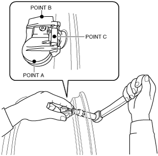
5. Completely tighten the valve nut using a torque wrench.
am6xuw00003644
|
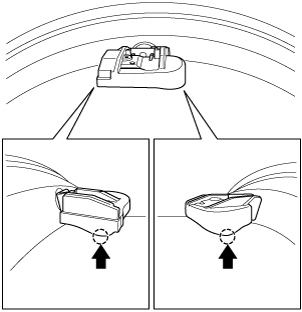
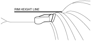
6. Verify that the wheel unit component is correctly installed.
am6xuw00003624
|
am6xuw00003625
|