 |
acmzzc00000021
DSC HU PART CONSTRUCTION/OPERATION
id041500100900
Construction
Function Of Main Component Parts
|
Part name |
Function |
|---|---|
|
Inlet solenoid valve
|
• Adjusts the fluid pressure in each brake system according to DSC HU/CM signals.
|
|
Outlet solenoid valve
|
• Adjusts the fluid pressure in each brake system according to DSC HU/CM signals.
|
|
Linear control solenoid valve
|
• Switches the brake hydraulic circuits during and according to normal braking, ABS and EBD control, TCS control and DSC control.
|
|
Reservoir
|
• Closes the hydraulic circuit between the master cylinder and reservoir if the brake pedal is depressed.
• Temporarily stores brake fluid from the caliper piston when pressure reduces during ABS and EBD controls.
• Opens the hydraulic circuit between the master cylinder and reservoir when pressure increases during TCS and DSC controls.
|
|
Pump
|
• Returns the brake fluid stored in the reservoir to the master cylinder during ABS and DSC control.
• Increases brake fluid pressure and sends brake fluid to each caliper piston during TCS control and DSC control.
|
|
Pump motor
|
• Operates the pump according to DSC HU/CM signals.
|
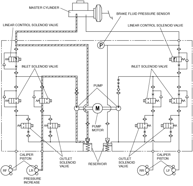
Hydraulic Circuit Diagram
acmzzc00000021
|
Operation
During normal braking
Solenoid valve operation table
|
Linear control solenoid valve |
Inlet solenoid valve |
Outlet solenoid valve |
Pump motor, pump |
|||||||
|---|---|---|---|---|---|---|---|---|---|---|
|
LF—RR |
RF—LR |
LF |
RF |
LR |
RR |
LF |
RF |
LR |
RR |
|
|
OFF (open)
|
OFF (open)
|
OFF (closed)
|
Stopped
|
|||||||
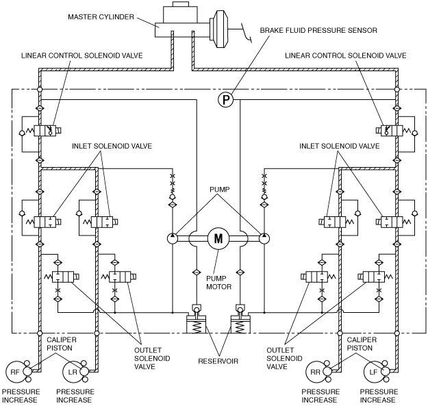
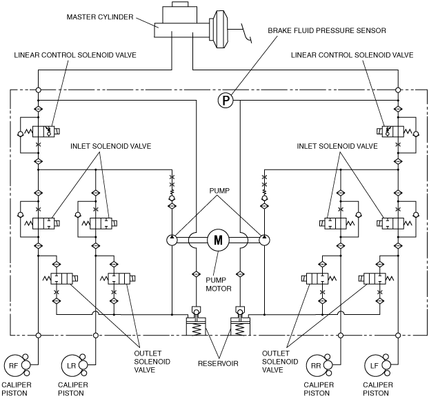
Hydraulic Circuit Diagram
acmzzc00000022
|
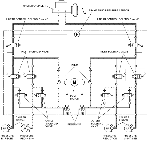
During ABS and EBD control
Solenoid valve operation table
|
|
Linear control solenoid valve |
Inlet solenoid valve |
Outlet solenoid valve |
Pump motor, pump |
|||||||
|---|---|---|---|---|---|---|---|---|---|---|---|
|
LF—RR |
RF—LR |
LF |
RF |
LR |
RR |
LF |
RF |
LR |
RR |
||
|
During pressure increase mode
|
OFF (open)
|
OFF (open)
|
OFF (closed)
|
Stopped
|
|||||||
|
During pressure maintain mode
|
OFF (open)
|
ON (closed)
|
OFF (closed)
|
Stopped
|
|||||||
|
During pressure reduction mode
|
OFF (open)
|
ON (closed)
|
ON (open)
|
Operating
|
|||||||
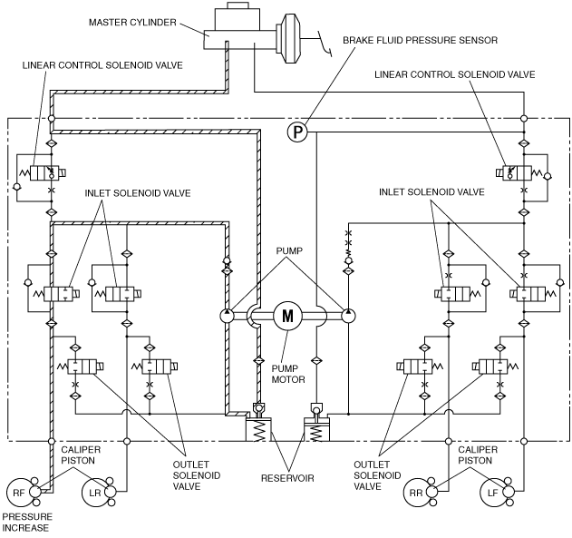
Hydraulic Circuit Diagram
acmzzc00000023
|
During TCS control
Solenoid valve operation table
|
|
Linear control solenoid valve |
Inlet solenoid valve |
Outlet solenoid valve |
Pump motor, pump |
|||||||
|---|---|---|---|---|---|---|---|---|---|---|---|
|
LF—RR |
RF—LR |
LF |
RF |
LR |
RR |
LF |
RF |
LR |
RR |
||
|
During pressure increase mode
|
OFF (open)
|
ON (adjusting pressure)
|
ON (closed)
|
OFF (open)
|
ON (closed)
|
OFF (closed)
|
Operating
|
||||
|
During pressure maintain mode
|
OFF (open)
|
ON (adjusting pressure)
|
ON (closed)
|
OFF (open)
|
ON (closed)
|
OFF (closed)
|
Operating
|
||||
|
During pressure reduction mode
|
OFF (open)
|
ON (adjusting pressure)
|
ON (closed)
|
OFF (open)
|
ON (closed)
|
OFF (closed)
|
Operating
|
||||
Hydraulic Circuit Diagram
acmzzc00000024
|
During DSC control (to suppress oversteer tendency)
Solenoid valve operation table
|
|
Linear control solenoid valve |
Inlet solenoid valve |
Outlet solenoid valve |
Pump motor, pump |
|||||||
|---|---|---|---|---|---|---|---|---|---|---|---|
|
LF—RR |
RF—LR |
LF |
RF |
LR |
RR |
LF |
RF |
LR |
RR |
||
|
During pressure increase mode
|
OFF (open)
|
ON (closed)
|
OFF (open)
|
ON (closed)
|
OFF (open)
|
OFF (closed)
|
ON (open)
|
OFF (closed)
|
Operating
|
||
|
During pressure maintain mode
|
OFF (open)
|
ON (closed)
|
OFF (open)
|
ON (closed)
|
OFF (open)
|
OFF (closed)
|
ON (open)
|
OFF (closed)
|
Operating
|
||
|
During pressure reduction mode
|
OFF (open)
|
ON (closed)
|
OFF (open)
|
ON (closed)
|
OFF (open)
|
OFF (closed)
|
ON (open)
|
OFF (closed)
|
Operating
|
||
Hydraulic Circuit Diagram
acmzzc00000025
|
During DSC control (to suppress understeer tendency)
Solenoid valve operation table
|
|
Linear control solenoid valve |
Inlet solenoid valve |
Outlet solenoid valve |
Pump motor, pump, |
|||||||
|---|---|---|---|---|---|---|---|---|---|---|---|
|
LF—RR |
RF—LR |
LF |
RF |
LR |
RR |
LF |
RF |
LR |
RR |
||
|
During pressure increase mode
|
OFF (open)
|
ON (closed)
|
OFF (open)
|
ON (closed)
|
OFF (open)
|
OFF (closed)
|
ON (open)
|
OFF (closed)
|
Operating
|
||
|
During pressure maintain mode
|
OFF (open)
|
ON (closed)
|
OFF (open)
|
ON (closed)
|
OFF (open)
|
OFF (closed)
|
ON (open)
|
OFF (closed)
|
Operating
|
||
|
During pressure reduction mode
|
OFF (open)
|
ON (closed)
|
OFF (open)
|
ON (closed)
|
OFF (open)
|
OFF (closed)
|
ON (open)
|
OFF (closed)
|
Operating
|
||
Hydraulic Circuit Diagram
acmzzc00000026
|