 |
am6zzw00000497
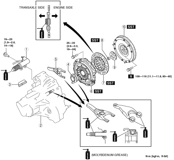
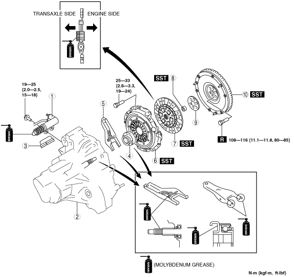
CLUTCH UNIT REMOVAL/INSTALLATION [L8, LF, L5]
id0510008003e4
1. Remove in the order indicated in the table.
2. Install in the reverse order removal.
L8, LF
am6zzw00000497
|
|
1
|
Clutch release cylinder
|
|
2
|
Manual transaxle
|
|
3
|
Boot
|
|
4
|
Clutch release collar
|
|
5
|
Clutch release fork
|
|
6
|
Clutch cover
|
|
7
|
Clutch disc
|
|
8
|
Pilot bearing
(See Pilot Bearing Removal Note.)
|
|
9
|
Plate (LF)
|
|
10
|
Flywheel
(See Flywheel Removal Note.)
(See Flywheel Installation Note.)
|
L5
am6zzw00000498
|
|
1
|
Clutch release cylinder
|
|
2
|
Manual transaxle
|
|
3
|
Boot
|
|
4
|
Clutch release collar
|
|
5
|
Clutch release fork
|
|
6
|
Clutch cover
|
|
7
|
Clutch disc
|
|
8
|
Pilot bearing
(See Pilot Bearing Removal Note.)
|
|
9
|
Plate
|
|
10
|
Flywheel
(See Flywheel Removal Note.)
(See Flywheel Installation Note.)
|
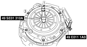
Clutch Cover and Disc Removal Note
1. Install the SSTs.
2. Loosen each bolt one turn at a time in a crisscross pattern until spring tension is released.
3. Remove the clutch cover and disc.
am6zzw00000499
|
Pilot Bearing Removal Note
1. Use the SST to remove the pilot bearing.
am6zzw00000500
|
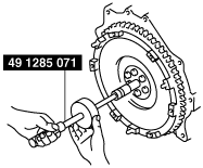
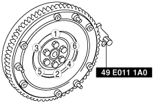
Flywheel Removal Note
1. Hold the flywheel using the SST.
2. Remove the bolts evenly and gradually in a crisscross pattern.
3. Remove the flywheel.
am6zzw00002841
|
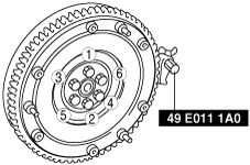
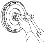
Flywheel Installation Note
1. Clean the crankshaft thread holes.
2. Install the flywheel to the crankshaft.
3. Hand‐tighten the new flywheel lock bolts.
4. Install the SST to the flywheel.
5. Gradually tighten the flywheel lock bolts in a crisscross pattern.
am6zzw00000501
|
6. Tighten the lock bolts in three steps in the order shown in the figure. (LF, L5)
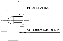
Pilot Bearing Installation Note
1. Install the pilot bearing using the corresponding 20 mm {0.79 in} side of a Snap-on brand millimeter size bushing driver set A160M adapter A160M7 (20—22 mm {0.79—0.86 in}) or substitution tool.
am6uuw00001257
|
am6zzw00000502
|
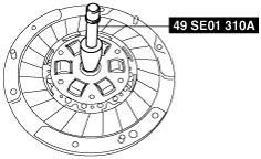
Clutch Disc Installation Note
1. Clean the splines of the clutch disc and the main drive gear with a brush.
2. Spread a thin layer of clutch grease on the splines.
3. Hold the clutch disc position using the SST.
am6zzw00000503
|
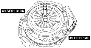
Clutch Cover Installation Note
1. Install the SSTs.
2. Tighten the bolts evenly and gradually in a crisscross pattern.
am6zzw00000504
|