MANUAL MODE SHIFT CONTROL OPERATION [FS5A-EL]


id051721102800


Manual mode shift

•  When the selector lever is shifted over from the D to M range position, the M range switch in the selector lever component turns on, sending a manual mode command signal to the TCM which activates the manual mode shift control.
•  When in manual mode and the selector lever is operated in the back (+) direction, the up switch in the selector lever component is turned on and an up-shift command signal is input to the TCM.
―  The TCM, triggered by the up-shift command signal, carries out shifting by outputting an operation signal to the shift solenoid if the ATF temperature is not low (for 4GR only), vehicle speed is higher than the set speed and the gear position is 4GR or lower.
•  Conversely, when the selector lever is operated in the forward (–) direction, the down switch in the selector lever component turns on, and a down-shift command signal is input to the TCM.
―  The TCM, triggered by the down-shift command signal, carries out shifting by outputting an operation signal to the shift solenoid if the vehicle speed is less than the set speed and the gear position is 2GR or above.
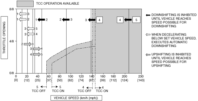
•  The TCM utilizes a specialized M range automatic shift diagram. Due to this, restriction of manual shift demand and automatic control of downshifting is carried out, reducing load on the ATX, preventing engine over-rev and ensuring drive stability.
•  If the engine reaches a high engine speed, the following controls are performed to protect the engine:
1.  To alert the driver that the engine speed has reached a high engine speed, the opening and closing of the throttle valve are repeated at regular intervals.
2.  The engine speed stabilizes at a lower speed than the excessive speed zone.
3.  If the engine speed reaches a high engine speed even if the above procedures are performed, a forced shift-up is performed to lower the engine speed.

Condition

Shift control

Note

2GR→3GR up-shift command at low speed
•  To reduce load on the ATX, upshifting is inhibited until vehicle reaches speed possible for upshifting
3GR→4GR up-shift command at low speed
4GR→5GR up-shift command at low speed
4GR→5GR up-shift command, low ATF temperature
•  To reduce load on the ATX, upshifting to 5GR is inhibited
5GR→4GR down-shift command, above set speed
•  To prevent engine over-rev, downshifting is inhibited until vehicle reaches speed possible for downshifting
•  Gear position indicator light flash to alert driver
4GR→3GR down-shift command, above set speed
3GR→2GR down-shift command, above set speed
2GR→1GR down-shift command, above set speed
In 5GR deceleration, speed goes below coast-down set speed (deceleration down- shift)
•  To assure drive stability, automatically downshifts from 5GR to 3GR
In 4GR deceleration, speed goes below coast-down set speed (deceleration down- shift)
•  To assure drive stability, automatically downshifts from 4GR to 3GR
In 3GR deceleration, speed goes below coast-down set speed (deceleration down- shift)
•  To assure drive stability, automatically downshifts from 3GR to 1GR
In 2GR deceleration, speed goes below coast-down set speed (deceleration down- shift)
•  To assure drive stability, automatically downshifts from 2GR to 1GR

Shift diagram

am6zzn00000838