VEHICLE SPEED SENSOR (VSS) INSPECTION [FS5A-EL]
id051721801400
Wave Profile Inspection
1. Inspect the power supply circuit for the VSS.
- (1) Remove the aerodynamic under cover NO.2. (SeeAERODYNAMIC UNDER COVER NO.2 REMOVAL/INSTALLATION.)
- (2) Disconnect the VSS connector.
-
- (3) Switch the ignition to ON.
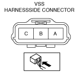
- (4) Measure the voltage at VSS connector terminal A (wiring harness side).
-
-
• If there is any malfunction, repair wiring harness between VSS and TCM.
-
Vehicle speed sensor (VSS) voltage
B+
- (5) Switch the ignition to OFF.
- (6) Connect the VSS connector.
2. Inspect the GND circuit for the VSS.
- (1) Switch the ignition to OFF.
- (2) Measure the voltage at VSS connector terminal C (wiring harness side).
-
-
• If there is any malfunction, repair wiring harness between VSS and TCM.
-
Vehicle speed sensor (VSS) voltage
Below 1.0 V
3. Inspect the signal circuit for the VSS.
- (1) Connect the oscilloscope to the following TCM connector terminals and set it as below.
-
-
• (+) lead: TCM terminal 2P
• (-) lead: TCM terminal 1P
• Oscilloscope setting: 1 V/DIV (Y), 2 ms/DIV (X), DC range
- (2) Start the engine.
- (3) Inspect wave profile when vehicle speed at 30 km/h {20mph}.
-
-
• If there is any malfunction, perform the Visual Inspection. (See
Visual Inspection.)
Visual Inspection
1. Shift the selector lever to N position.
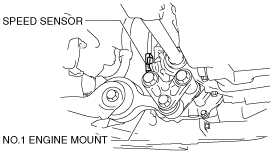
2. Remove the VSS.
- (1) Disconnect the negative battery cable.
- (2) Remove the aerodynamic under cover NO.2. (SeeAERODYNAMIC UNDER COVER NO.2 REMOVAL/INSTALLATION.)
- (3) Disconnect the VSS connector.
-
- (4) Remove the VSS from the transaxle case.
3. Verify that the sensor is free of any metallic shavings or particles.
-
• If there is any malfunction, clean them off.
4. Inspect sensor rotor surface via VSS installation hole while rotating the front tire manually.
- (1) Is sensor rotor free of damage and cracks?
- (2) Is sensor rotor free of any metallic shavings or particles?
-
-
• If there is any malfunction, clean or replace the sensor rotor.