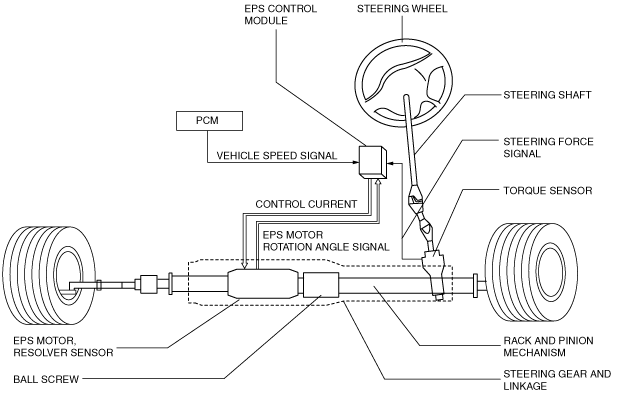
ELECTRIC POWER STEERING (EPS) CONSTRUCTION AND OPERATION


id061300246300


Construction

•  The EPS system consists of the following parts:
―  Manual steering mechanism:
Consists of the steering wheel, steering shaft, steering gear and linkage.
―  Electric assist mechanism:
Consists of the EPS motor and ball screw built into the steering gear and linkage.
―  Control system:
Consists of a torque sensor, resolver sensor, and vehicle speed signals input from the EPS control module and PCM.
am6zzn00000479

Operation

•  The EPS assists the manual steering mechanism operation using the EPS motor to provide supplemental manual power during vehicle steering, reducing the load on the driver.

Manual steering mechanism operation

•  The steering input force, formed when the driver operates the steering wheel, is converted from a rotational movement to a linear movement by the rack and pinion mechanism of the steering gear and linkage. This linear movement is transmitted via the inner and outer ball joints to the steering knuckle to steer the tires left or right.


Power assist mechanism operation

•  The torque sensor detects the steering force (road surface resistance) and the resolver sensor detects the rotor position of the EPS motor according to the steering action of the driver. The torque sensor outputs a steering signal and the resolver sensor outputs an EPS motor rotation angle signal to the EPS control module.
•  The EPS control module performs various control corrections based on the steering force signal, EPS motor rotation angle signal, vehicle speed, and other vehicle conditions, and determines the optimum power assist force.
•  Based on the assist force determined by the EPS control module, the current from the motor drive circuit to the EPS motor is controlled to within the target current amount to operate the motor correctly.
•  The operating force generated by the EPS motor rotates the ball screw integrated with the motor to assist the axial movement of the rack. As a result, the steering operation load on the driver is reduced.


Component parts and function

Part name

Function

Steering gear and linkage
Torque sensor
•  Detects the steering force and inputs it to the EPS control module.
Resolver sensor
•  Detects the motor rotation angle and inputs it to the EPS control module.
EPS motor
•  Generates assist force based on the control current from the EPS control module.
EPS control module
•  Determines the control current for the EPS motor based on the steering force signal from the torque sensor, vehicle speed signal from the PCM and other signals.
•  Inputs an idle increase command signal to the PCM via CAN lines.
•  Controls the on-board diagnostic system and fail-safe function when a malfunction is detected in the EPS system.
PCM
Vehicle speed signal
•  Inputs the vehicle speed signal to the EPS control module via CAN lines.
Engine speed signal
•  Inputs the engine speed signal to the EPS control module via CAN lines.
Instrument cluster
EPS warning light
•  The light illuminates to inform the driver when a system malfunction is detected.