|
am6zzn00000252
ELECTRIC POWER STEERING (EPS) CONTROL MODULE CONSTRUCTION AND OPERATION
id061300247100
Construction
Function Table
|
Control item |
Function |
|---|---|
|
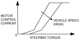
Motor current control
|
• Calculates the optimum assist current based on the steering force, motor rotation angle, and vehicle and engine speeds, and outputs a control current to the EPS motor.
|
|
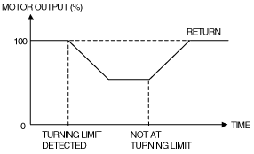
System overheating prevention control
|
• In order to prevent system overheating, motor current is controlled according to the turning limit or motor output control.
|
|
On-board diagnostic function
|
• The main part of the system control includes the self-diagnosis function. In case a malfunction occurs, the EPS warning light illuminates to alert the driver, and a DTC is stored in the EPS control module at the same time.
• As a result of the on-board diagnosis, when a malfunction is determined, system control is suspended or limited to assure safety while driving.
|
am6zzn00000252
|
Operation
Motor current control
am6zzn00000253
|
am6zzn00000254
|
System overheating prevention control
am6zzn00000255
|
am6zzn00000256
|