 |
am6zzw00007938
STEERING GEAR AND LINKAGE ADJUSTMENT
id061300290000
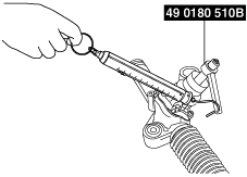
1. Remove the locknut using the SST.
am6zzw00007938
|
2. Apply sealant to the threads of the adjustment cover.
3. Tighten the adjustment cover to 20—29 N·m {2.1—2.9 kgf·m, 15—21 ft·lbf}.
4. After swinging the steering rack left and right 10 times, tighten the adjustment cover again.
Tightening torque
|
Tightening torque
|
8.0 N·m {82 kgf·cm, 71 in·lbf}
|
5.8 N·m {59 kgf·cm, 51 in·lbf}
|
|
Applicable VIN (assumed)
|
European (L.H.D.) specs.
JMZ GH12***# 100001—261049
JMZ GH14***# 100001—261049
JMZ GH19**0# 100001—261049
U.K. specs.
JMZ GH12**0# 100001—261049
JMZ GH14**0# 100001—261049
JMZ GH19**0# 100001—261049
Australian specs.
JM0 GH10*100 100001—137422
General (L.H.D.) specs.
GH10*1 100001—137416
JM7 GH32***# 100001—137416
JM7 GH34***# 100001—137416
JM7 GH39***# 100001—137416
JM7 GH42***# 100001—137416
JM7 GH44***# 100001—137416
JM7 GH49***# 100001—137416
General (R.H.D.) specs.
JM6 GH10*1*0 100001—137416
|
European (L.H.D.) specs.
JMZ GH12***# 261050—
JMZ GH14***# 261050—
JMZ GH19**0# 261050—
U.K. specs.
JMZ GH12**0# 261050—
JMZ GH14**0# 261050—
JMZ GH19**0# 261050—
Australian specs.
JM0 GH10*100 137423—
General (L.H.D.) specs.
GH10*1 137417—
JM7 GH32***# 137417—
JM7 GH34***# 137417—
JM7 GH39***# 137417—
JM7 GH42***# 137417—
JM7 GH44***# 137417—
JM7 GH49***# 137417—
General (R.H.D.) specs.
JM6 GH10*1*0 137417—
|
am6zzw00003700
|
5. Loosen the adjustment cover 10—20°.
am6zzw00001707
|
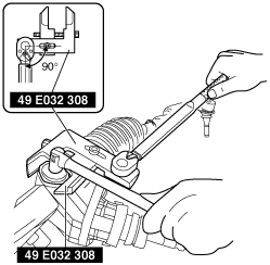
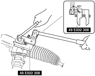
6. Combine the the SST with the torque wrench, then measure A and L as shown in the figure.
am6zzw00007934
|
7. Recalculate the torque by using torque formulas, then lock the adjustment cover against rotation and tighten the locknut using the SST.
am6zzw00007939
|
Torque formula
|
Torque unit |
Formula |
|---|---|
|
N·m
|
N·m×[L/A]
|
|
kgf·m
|
kgf·m×[L/A]
|
|
ft·lbf
|
ft·lbf×[L/A]
|
8. Measure the pinion shaft rotational torque using the SST and a pull scale.
am6zzw00003698
|