 |
am6zzw00000258
DTC U3003:16/U3003:17 [BCM]
id0902f5310100
Malfunction Location
Detection Condition
Possible Causes
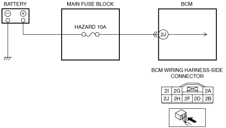
System Wiring Diagram
am6zzw00000258
|
Diagnostic Procedure
|
Step |
Inspection |
Action |
|
|---|---|---|---|
|
1
|
BATTERY INSPECTION
• Disconnect the battery cables.
• Refer to the battery inspection and inspect the battery.
• Is the battery normal?
|
Yes
|
Go to step 4.
|
|
No
|
Go to the next step.
|
||
|
2
|
INSPECT GENERATOR CONNECTOR CONDITION
• Disconnect the generator connector.
• Inspect for proper connector connections, connection conditions, damage, rust, or deformation.
• Is the connector normal?
|
Yes
|
Go to the next step.
|
|
No
|
Repair/replace the connector.
After repair procedure, go to Step 8.
|
||
|
3
|
INSPECT GENERATOR
• Is the generator normal?
|
Yes
|
Replace/charge the battery.
|
|
No
|
Replace the generator.
After replacement, go to Step 8.
|
||
|
4
|
FUSE INSPECTION
• Remove the HAZARD 10 A fuse.
• Is the fuse normal?
|
Yes
|
Go to the next step.
|
|
No
|
Replace the fuse.
After replacement, go to Step 8.
|
||
|
5
|
INSPECT BCM CONNECTOR CONDITION
• Disconnect the BCM connector.
• Inspect for proper connector connections, connection conditions, damage, rust, or deformation.
• Is the connector normal?
|
Yes
|
Go to the next step.
|
|
No
|
Repair/replace the connector.
After repair procedure, go to step 8.
|
||
|
6
|
INSPECT BCM POWER SUPPLY CIRCUIT FOR SHORT CIRCUIT TO GROUND
• Inspect for continuity between BCM terminal 2J and body ground.
• Is there continuity?
|
Yes
|
Repair/replace the wiring harness.
After repair procedure, go to step 8.
|
|
No
|
Go to the next step.
|
||
|
7
|
INSPECT BCM POWER SUPPLY CIRCUIT FOR OPEN CIRCUIT
• Inspect for continuity between BCM terminal 2J and battery positive terminal.
• Is there continuity?
|
Yes
|
Go to the next step.
|
|
No
|
Repair/replace the wiring harness.
After repair procedure, go to the next step.
|
||
|
8
|
Verify DTC
• Install the fuse.
• Reconnect the disconnected connectors and battery cables, then switch the ignition to ON.
• Clear the DTC from the BCM memory using the M-MDS.
(See CLEARING DTC [BCM].)
• Switch the ignition to off , then ON.
• Perform the BCM DTC inspection using the M-MDS.
(See DTC INSPECTION [BCM].)
• Is the same DTC present?
|
Yes
|
Return to Step 1, and inspect for other malfunction locations.
If the malfunction recurs, replace the BCM.
Go to the next step.
|
|
No
|
Go to the next step.
|
||
|
9
|
VERIFY THAT NO OTHER DTCs ARE PRESENT
• Are there other DTCs output?
|
Yes
|
Perform the corresponding DTC inspection.
|
|
No
|
DTC troubleshooting completed.
|
||