 |
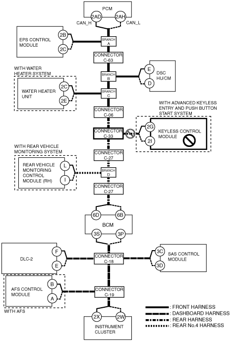
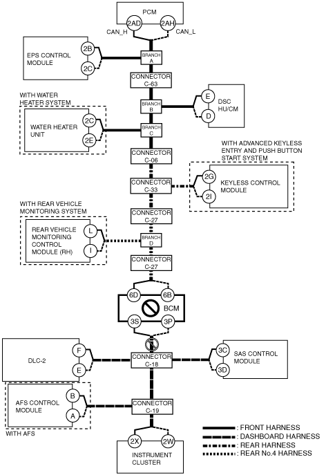
am6zzw00003945
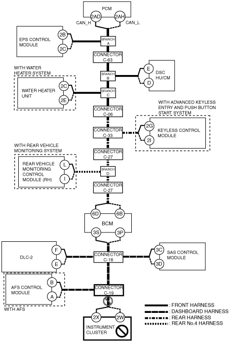
DETERMINING MALFUNCTIONING PART (HS-CAN) [MULTIPLEX COMMUNICATION SYSTEM (MZR-CD 2.2)]
id0902j5846700
1. Verify the CAN system-related module DTCs and the failed module on the M-MDS screen.
2. Refer to “DTC Output Pattern and Malfunctioning Part” and find the area linked from the malfunctioning part.
3. Inspect the possible cause and inspection item of the applicable malfunctioning part.
4. Perform the DTC inspection after the repair procedure.
DTC Output Pattern and Malfunctioning Part
|
M-MDS display |
DTC output pattern and malfunctioning part |
||||||||||||||||
|---|---|---|---|---|---|---|---|---|---|---|---|---|---|---|---|---|---|
|
DTC output module |
DTC |
||||||||||||||||
|
PCM
(PCM)
|
U0121:00
|
|
|
|
×
|
|
|
|
|
|
|
|
|
|
|
|
|
|
U0155:00
|
|
|
|
|
|
|
|
|
|
|
|
|
|
|
|
×
|
|
|
EPS
(EPS control module)
|
U0100:00
|
×
|
|
|
|
|
|
|
|
|
|
|
|
|
|
|
|
|
U0401:00
|
-
|
|
|
|
|
|
|
|
|
|
|
|
|
|
|
|
|
|
ABS
(DSC HU/CM)
|
U0100:00
|
×
|
|
×
|
|
|
|
|
|
|
|
|
|
|
|
|
|
|
U0140:00
|
|
|
|
|
|
|
|
|
|
|
|
|
|
|
|
|
|
|
U0155:00
|
|
|
|
|
|
|
|
|
|
|
|
|
|
|
|
×
|
|
|
U0214:00
|
|
|
|
|
|
|
|
×
|
|
|
|
|
|
|
|
|
|
|
U0401:00
|
-
|
|
-
|
|
|
|
|
|
|
|
|
|
|
|
|
|
|
|
U0401:68
|
-
|
|
-
|
|
|
|
|
|
|
|
|
|
|
|
|
|
|
|
FFH*1
(Water heater unit)
|
U0100:00
|
×
|
|
×
|
|
×
|
|
|
|
|
|
|
|
|
|
|
|
|
U0140:00
|
|
|
|
|
|
|
|
|
|
|
|
|
|
|
|
|
|
|
U0155:00
|
|
|
|
|
|
|
|
|
|
|
|
|
|
|
|
×
|
|
|
RKE*2
(Keyless control module)
|
U0100:00
|
×
|
|
×
|
|
×
|
|
×
|
|
|
|
|
|
|
|
|
|
|
U0121:00
|
|
|
|
×
|
×
|
|
×
|
|
|
|
|
|
|
|
|
|
|
|
U0401:68
|
-
|
|
-
|
|
-
|
|
-
|
|
|
|
|
|
|
|
|
|
|
|
RVM*3
(Rear vehicle monitoring control module (RH))
|
U0100:00
|
×
|
|
×
|
|
×
|
|
×
|
|
×
|
|
|
|
|
|
|
|
|
U0121:00
|
|
|
|
×
|
×
|
|
×
|
|
×
|
|
|
|
|
|
|
|
|
|
U0140:00
|
|
|
|
|
|
|
|
|
|
|
|
|
|
|
|
|
|
|
U0155:00
|
|
|
|
|
|
|
|
|
|
|
|
|
|
|
|
×
|
|
|
U0401:68
|
-
|
|
-
|
|
-
|
|
-
|
|
-
|
|
|
|
|
|
|
|
|
|
U0415:68
|
|
|
|
-
|
-
|
|
-
|
|
-
|
|
|
|
|
|
|
|
|
|
BCM/GEM
(BCM)
|
U0100:00
|
×
|
|
×
|
|
×
|
|
×
|
|
×
|
|
×
|
|
|
|
|
|
|
U0151:00
|
|
|
|
|
|
|
|
|
|
|
|
|
×
|
|
|
|
|
|
U0214:00
|
|
|
|
|
|
|
|
×
|
×
|
|
×
|
|
|
|
|
|
|
|
U0401:68
|
-
|
|
-
|
|
-
|
|
-
|
|
-
|
|
-
|
|
|
|
|
|
|
|
RCM
(SAS control module)
|
U0155:00
|
|
|
|
|
|
|
|
|
|
|
|
|
|
|
|
×
|
|
IC
(Instrument cluster)
|
U0100:00
|
×
|
|
×
|
|
×
|
|
×
|
|
×
|
|
×
|
×
|
|
×
|
|
|
|
U0100:87
|
-
|
|
-
|
|
-
|
|
-
|
|
-
|
|
-
|
-
|
|
-
|
|
|
|
|
U0121:00
|
|
|
|
×
|
×
|
|
×
|
|
×
|
|
×
|
×
|
|
×
|
|
|
|
|
U0131:00
|
|
×
|
×
|
|
×
|
|
×
|
|
×
|
|
×
|
×
|
|
×
|
|
|
|
|
U0140:00
|
|
|
|
|
|
|
|
|
|
|
|
×
|
|
×
|
|
|
|
|
U0151:00
|
|
|
|
|
|
|
|
|
|
|
|
|
×
|
×
|
|
|
|
|
U0166:00
|
|
|
|
|
|
×
|
×
|
|
×
|
|
×
|
×
|
|
×
|
|
|
|
|
U0182:00
|
|
|
|
|
|
|
|
|
|
|
|
|
|
|
×
|
|
|
|
U0214:00
|
|
|
|
|
|
|
|
×
|
×
|
|
×
|
×
|
|
×
|
|
|
|
|
U0232:00
|
|
|
|
|
|
|
|
|
|
×
|
×
|
×
|
|
×
|
|
|
|
|
U0401:68
|
-
|
|
-
|
|
-
|
|
-
|
|
-
|
|
-
|
-
|
|
-
|
|
|
|
|
U0415:68
|
|
|
|
-
|
-
|
|
-
|
|
-
|
|
-
|
-
|
|
-
|
|
|
|
|
U0515:68
|
|
|
|
|
|
|
|
-
|
-
|
|
-
|
-
|
|
-
|
|
|
|
|
M-MDS display module
|
“Fail” display pattern
|
||||||||||||||||
|
PCM
|
×
|
|
×
|
|
×
|
|
×
|
|
×
|
|
×
|
×
|
|
×
|
|
|
|
|
EPS
|
|
×
|
×
|
|
×
|
|
×
|
|
×
|
|
×
|
×
|
|
×
|
|
|
|
|
ABS
|
|
|
|
×
|
×
|
|
×
|
|
×
|
|
×
|
×
|
|
×
|
|
|
|
|
FFH
|
|
|
|
|
|
×
|
×
|
|
×
|
|
×
|
×
|
|
×
|
|
|
|
|
RKE
|
|
|
|
|
|
|
|
×
|
×
|
|
×
|
×
|
|
×
|
|
|
|
|
RVM
|
|
|
|
|
|
|
|
|
|
×
|
×
|
×
|
|
×
|
|
|
|
|
BCM/GEM
|
|
|
|
|
|
|
|
|
|
|
|
×
|
|
×
|
|
|
|
|
SAS
|
|
|
|
|
|
|
|
|
|
|
|
|
×
|
×
|
|
|
|
|
IC
|
|
|
|
|
|
|
|
|
|
|
|
|
|
|
|
×
|
|
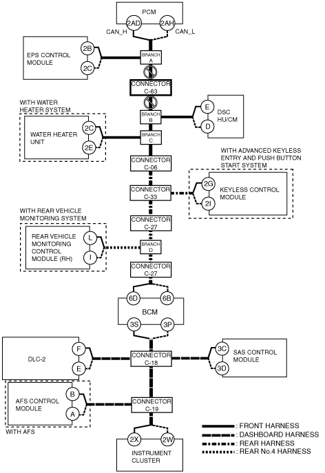
A
Possible cause
System wiring diagram
am6zzw00003945
|
Inspection item
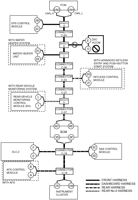
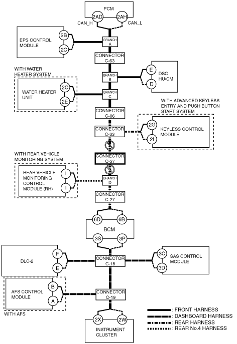
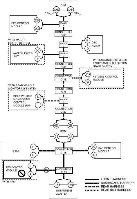
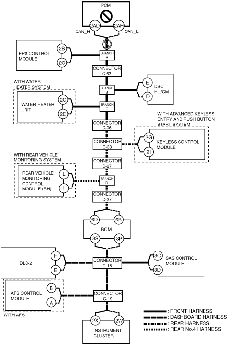
B
Possible cause
System wiring diagram
am6zzw00003946
|
Inspection item
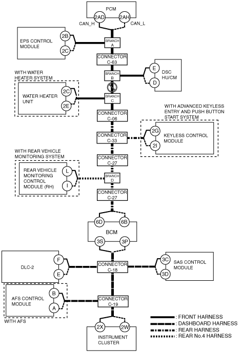
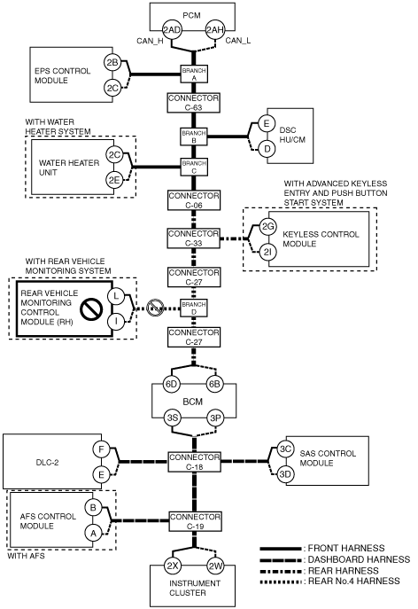
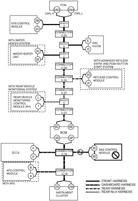
C
Possible cause
System wiring diagram
am6zzw00003947
|
Inspection item
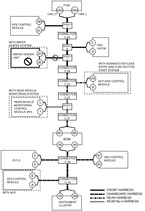
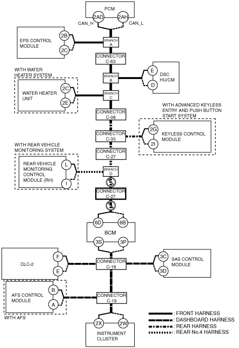
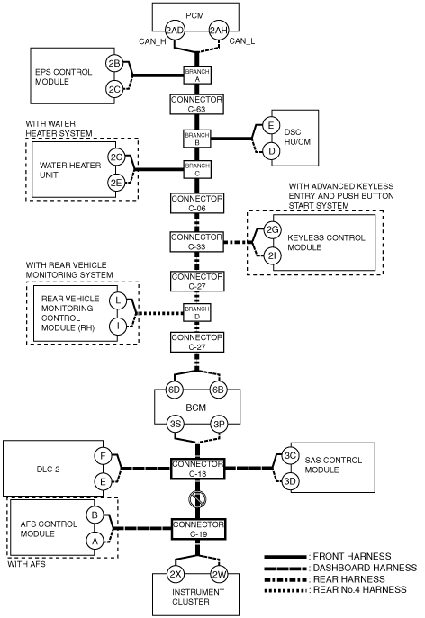
D
Possible cause
System wiring diagram
am6zzw00003948
|
Inspection item
E
Possible cause
System wiring diagram
am6zzw00003949
|
Inspection item
F
Possible cause
System wiring diagram
am6zzw00003950
|
Inspection item
G
Possible cause
System wiring diagram
am6zzw00003951
|
Inspection item
H
Possible cause
System wiring diagram
am6zzw00003952
|
Inspection item
I
Possible cause
System wiring diagram
am6zzw00003953
|
Inspection item
J
Possible cause
System wiring diagram
am6zzw00003954
|
Inspection item
K
Possible cause
System wiring diagram
am6zzw00003955
|
Inspection item
L
Possible cause
System wiring diagram
am6zzw00003956
|
Inspection item
M
Possible cause
System wiring diagram
am6zzw00003957
|
Inspection item
N
Possible cause
System wiring diagram
am6zzw00003958
|
Inspection item
O
Possible cause
System wiring diagram
am6zzw00003959
|
Inspection item
P
Possible cause
System wiring diagram
am6zzw00003960
|
Inspection item