DETERMINING MALFUNCTIONING PART (MS-CAN) [MULTIPLEX COMMUNICATION SYSTEM (MZR-CD 2.2)]
id0902j5846800
-
Caution
-
• If the malfunctioning part is detected in the communication line, before disconnecting the related connector for inspection, press the connector in the connection direction to verify that there is no looseness or disconnection.
• When disconnecting the connector, verify that there is no damage, deformation, or corrosion of the connector terminals.
1. Verify DTCs of the modules related to the CAN system.
2. Apply the following items to the DTC Output Pattern and Malfunctioning Part, and then verify the reference to the malfunctioning location.
-
• Communication error DTCs
• Malfunctioning module
• Display status of the air conditioner/audio control on the information display when the climate control unit, or either the audio unit or the car-navigation unit is operated.
• The operation condition of the hands-free telephone (HF/TEL) system.
-
Note
-
• A hyphen (-) in the DTC output pattern cell indicates that the DTC may or may not be displayed depending on the malfunction detection conditions. If it is not displayed, the malfunctioning location can be determined by checking the crosses (×) and asterisks (*).
3. Inspect the possible cause and inspection item of the applicable malfunctioning part.
4. Perform the DTC inspection after the repair procedure.
-
DTC Output Pattern and Malfunctioning Part
Cross (×): Displayed
Hyphen (-): May or may not be displayed
Asterisk (*): No display or no operation
|
DTC display
|
DTC output pattern and malfunctioning location
|
|
DTC output module
|
DTC
|
|
|
|
|
|
|
|
IC*1
(Instrument cluster)
|
U0164:00
|
|
|
×
|
|
|
|
|
EATC*1
(Climate control unit)
|
U0155:00
|
|
|
|
×
|
|
×
|
|
U0184:00
|
|
×
|
|
|
|
|
|
U0423:68
|
|
|
|
-
|
|
-
|
|
Information display*2
|
U015500HEC
|
×
|
|
|
×
|
|
×
|
|
U016400EATC
|
×
|
|
×
|
|
|
|
|
U018400ACU
|
×
|
×
|
|
|
|
|
|
Audio unit (with audio unit)*2
|
16:Er11
|
|
-
|
|
-
|
|
-
|
|
17:Er11
|
|
-
|
|
-
|
|
-
|
|
Car-navigation unit (with car-navigation unit)*3
|
Device code 17/error code 11
|
|
-
|
|
-
|
|
-
|
|
M-MDS display module
|
“Fail” display pattern
|
|
IC
|
|
|
|
×
|
|
×
|
|
EATC
|
|
|
×
|
|
|
|
|
Information display display
|
Display pattern on information display
|
|
None ACU*4
|
-
|
-
|
|
|
|
|
|
None EATC*5
|
-
|
|
-
|
|
|
|
|
Audio control display
|
*
|
*
|
|
|
|
|
|
Air conditioning control display
|
*
|
|
*
|
|
|
|
|
System operation
|
System operation pattern
|
|
Hands-free telephone system
|
|
*
|
|
*
|
*
|
|
*1 :The DTC is displayed on M-MDS.
*2 :The DTC is displayed on the information display.
*3 :The DTC is displayed on the car navigation unit.
*4 :If “None ACU” is displayed on the information display, no DTC is displayed.
*5 :If “None EATC” is displayed on the information display, no DTC is displayed.
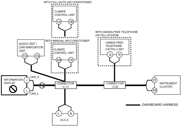
A
Possible cause
-
• Connector terminal disconnection, poor contact, damage, deformation, corrosion
• Open circuit in wiring harness between information display and connector C-17
• Information display malfunction
System wiring diagram
Inspection item
-
• Information display connector
• Connector C-17
• Wiring harness between information display terminal J and connector C-17
• Wiring harness between information display terminal L and connector C-17
• Information display
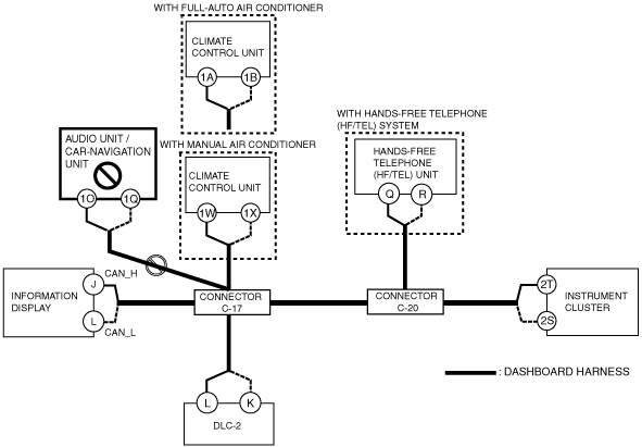
B
Possible cause
-
• Connector terminal disconnection, poor contact, damage, deformation, corrosion
• Open circuit in wiring harness between car-navigation unit or audio unit and connector C-17
• Car-navigation unit or audio unit malfunction
System wiring diagram
Inspection item
-
• Car-navigation unit or audio unit connector
• Connector C-17
• Wiring harness between car-navigation unit or audio unit terminal 1O and connector C-17
• Wiring harness between car-navigation unit or audio unit terminal 1Q and connector C-17
• Car-navigation unit or audio unit
C
Possible cause
-
• Connector terminal disconnection, poor contact, damage, deformation, corrosion
• Open circuit in wiring harness between climate control unit and connector C-17
• Climate control unit malfunction
System wiring diagram
Inspection item
-
• Climate control unit connector
• Connector C-17
• Wiring harness between climate control unit terminal 1A and connector C-17 (with full-auto air conditioner)
• Wiring harness between climate control unit terminal 1B and connector C-17 (with full-auto air conditioner)
• Wiring harness between climate control unit terminal 1W and connector C-17 (with manual air conditioner)
• Wiring harness between climate control unit terminal 1X and connector C-17 (with manual air conditioner)
• Climate control unit
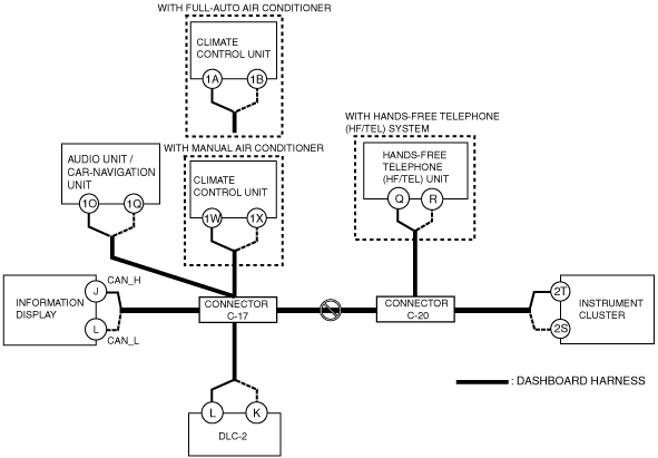
D
Possible cause
-
• Connector terminal disconnection, poor contact, damage, deformation, corrosion
• Open circuit in wiring harness between connector C-17 and connector C-20
System wiring diagram
Inspection item
-
• Connector C-17
• Connector C-20
• Wiring harness between connector C-17 and connector C-20
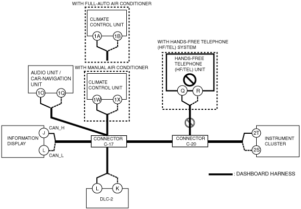
E
Possible cause
-
• Connector terminal disconnection, poor contact, damage, deformation, corrosion
• Open circuit in wiring harness between HF/TEL unit and connector C-20
• HF/TEL unit malfunction
System wiring diagram
Inspection item
-
• HF/TEL unit connector
• Connector C-20
• Wiring harness between HF/TEL unit terminal Q and connector C-20
• Wiring harness between HF/TEL unit terminal R and connector C-20
• HF/TEL unit
F
Possible cause
-
• Connector terminal disconnection, poor contact, damage, deformation, corrosion
• Open circuit in wiring harness between instrument cluster and connector C-20
• Instrument cluster malfunction
System wiring diagram
Inspection item
-
• Instrument cluster connector
• Connector C-20
• Wiring harness between instrument cluster terminal 2T and connector C-20
• Wiring harness between instrument cluster terminal 2S and connector C-20
• Instrument cluster