 |
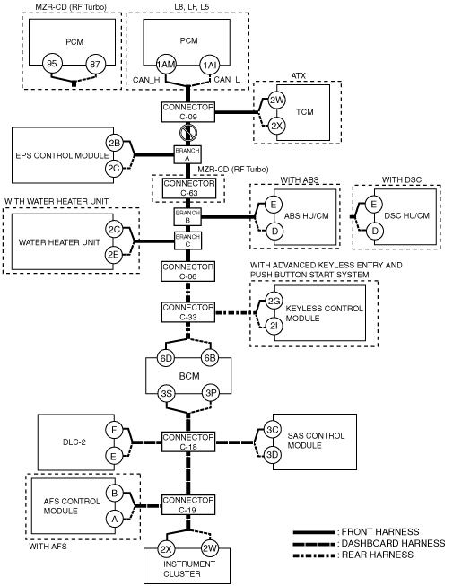
am6zzw00003963
DETERMINING MALFUNCTIONING PART (HS-CAN) [MULTIPLEX COMMUNICATION SYSTEM (L8, LF, L5, MZR-CD (RF Turbo))]
id0902j6846700
1. Verify the CAN system-related module DTCs and the failed module on the M-MDS screen.
2. Refer to “DTC Output Pattern and Malfunctioning Part” and find the area linked from the malfunctioning part.
3. Inspect the possible cause and inspection item of the applicable malfunctioning part.
4. Perform the DTC inspection after the repair procedure.
DTC Output Pattern and Malfunctioning Part
|
M-MDS display |
DTC output pattern and malfunctioning part |
|||||||||||||||
|---|---|---|---|---|---|---|---|---|---|---|---|---|---|---|---|---|
|
DTC output module |
DTC |
|||||||||||||||
|
IC
(Instrument cluster)
|
U0100:00
|
×
|
|
×
|
|
×
|
|
×
|
|
×
|
|
×
|
×
|
|
|
×
|
|
U0100:87
|
-
|
|
-
|
|
-
|
|
-
|
|
-
|
|
-
|
-
|
|
|
-
|
|
|
U0101:00
|
|
×
|
×
|
|
×
|
|
×
|
|
×
|
|
×
|
×
|
|
|
×
|
|
|
U0121:00
|
|
|
|
|
|
×
|
×
|
|
×
|
|
×
|
×
|
|
|
×
|
|
|
U0131:00
|
|
|
|
×
|
×
|
|
×
|
|
×
|
|
×
|
×
|
|
|
×
|
|
|
U0140:00
|
|
|
|
|
|
|
|
|
|
|
|
×
|
|
|
×
|
|
|
U0151:00
|
|
|
|
|
|
|
|
|
|
|
|
|
|
×
|
×
|
|
|
U0166:00
|
|
|
|
|
|
|
|
×
|
×
|
|
×
|
×
|
|
|
×
|
|
|
U0182:00
|
|
|
|
|
|
|
|
|
|
|
|
|
×
|
|
×
|
|
|
U0214:00
|
|
|
|
|
|
|
|
|
|
×
|
×
|
×
|
|
|
×
|
|
|
U0401:68
|
-
|
|
-
|
|
-
|
|
-
|
|
-
|
|
-
|
-
|
|
|
|
|
|
U0402:68
|
|
-
|
-
|
|
-
|
|
-
|
|
-
|
|
-
|
-
|
|
|
|
|
|
U0415:68
|
|
|
|
|
|
-
|
|
|
-
|
|
-
|
-
|
|
|
|
|
|
U0515:68
|
|
|
|
|
|
|
|
|
|
-
|
-
|
-
|
|
|
|
|
|
PCM
(PCM (L8, LF, L5))
|
U0101:00
|
|
×
|
|
|
|
|
|
|
|
|
|
|
|
|
|
|
U0121:00
|
|
|
|
|
|
×
|
|
|
|
|
|
|
|
|
|
|
|
U0131:00
|
|
|
|
×
|
|
|
|
|
|
|
|
|
|
|
|
|
|
U0140:00
|
|
|
|
|
|
|
|
|
|
|
|
|
|
|
|
|
|
U0151:00
|
|
|
|
|
|
|
|
|
|
|
|
|
|
×
|
|
|
|
U0155:00
|
|
|
|
|
|
|
|
|
|
|
|
|
|
|
|
|
|
PCM
(PCM (MZR-CD (RF Turbo)))
|
U0121:00
|
|
|
|
|
|
×
|
|
|
|
|
|
|
|
|
|
|
U0155:00
|
|
|
|
|
|
|
|
|
|
|
|
|
|
|
|
|
|
TCM*3
(TCM)
|
U0100:00
|
×
|
|
|
|
|
|
|
|
|
|
|
|
|
|
|
|
EPS
(EPS control module)
|
U0100:00
|
×
|
|
×
|
|
|
|
|
|
|
|
|
|
|
|
|
|
U0401:00
|
-
|
|
-
|
|
|
-
|
|
|
|
|
|
|
|
|
|
|
|
ABS*1
(ABS HU/CM)
|
U0100:00
|
×
|
|
×
|
|
×
|
|
|
|
|
|
|
|
|
|
|
|
U0214:00
|
|
|
|
|
|
|
|
|
|
×
|
|
|
|
|
|
|
|
ABS*2
(DSC HU/CM)
|
U0100:00
|
×
|
|
×
|
|
×
|
|
|
|
|
-
|
|
|
|
|
|
|
U0101:00
|
|
×
|
-
|
|
-
|
|
|
|
|
-
|
|
|
|
|
|
|
|
U0140:00
|
|
|
|
|
|
|
|
|
|
-
|
|
|
|
|
|
|
|
U0155:00
|
|
|
|
|
|
|
|
|
|
-
|
|
|
|
|
|
|
|
U0214:00
|
|
|
|
|
|
|
|
|
|
×
|
|
|
|
|
|
|
|
U0401:00
|
-
|
|
-
|
|
-
|
|
|
|
|
|
|
|
|
|
|
|
|
U0401:68
|
-
|
|
-
|
|
-
|
|
|
|
|
|
|
|
|
|
|
|
|
U0402:00
|
|
-
|
-
|
|
-
|
|
|
|
|
|
|
|
|
|
|
|
|
FFH
(Water heater unit (with water heater system))
|
U0100:00
|
×
|
|
×
|
|
×
|
|
×
|
|
|
|
|
|
|
|
|
|
U0140:00
|
|
|
|
|
|
|
|
|
|
|
|
|
|
|
|
|
|
U0155:00
|
|
|
|
|
|
|
|
|
|
|
|
|
|
|
|
|
|
RKE
(Keyless control module (with advanced keyless entry and start system))
|
U0100:00
|
×
|
|
×
|
|
×
|
|
×
|
|
×
|
|
|
|
|
|
|
|
U0100:87
|
-
|
|
-
|
|
-
|
|
-
|
|
-
|
|
|
|
|
|
-
|
|
|
U0101:00
|
|
×
|
×
|
|
×
|
|
×
|
|
×
|
|
|
|
|
|
|
|
|
U0121:00
|
|
|
|
|
|
×
|
-
|
|
-
|
|
|
|
|
|
|
|
|
U0401:68
|
-
|
|
-
|
|
-
|
|
-
|
|
-
|
|
|
|
|
|
|
|
|
BCM/GEM
(BCM)
|
U0100:00
|
×
|
|
×
|
|
×
|
|
×
|
|
×
|
|
×
|
|
|
|
|
|
U0101:00
|
|
×
|
×
|
|
×
|
|
×
|
|
×
|
|
×
|
|
|
|
|
|
|
U0151:00
|
|
|
|
|
|
|
|
|
|
|
|
|
|
×
|
|
|
|
U0214:00
|
|
|
|
|
|
|
|
|
|
×
|
×
|
|
|
|
|
|
|
U0401:68
|
-
|
|
-
|
|
-
|
-
|
-
|
|
-
|
|
-
|
|
|
|
-
|
|
|
U0402:68
|
|
-
|
-
|
|
-
|
|
-
|
|
-
|
|
-
|
|
|
|
|
|
|
RCM
(SAS control module)
|
U0155:00
|
|
|
|
|
|
|
|
|
|
|
|
|
|
|
|
|
M-MDS display module
|
“Fail” display pattern
|
|||||||||||||||
|
PCM
|
×
|
|
×
|
|
×
|
|
×
|
|
×
|
|
×
|
×
|
|
|
×
|
|
|
TCM*3
|
|
×
|
×
|
|
×
|
|
×
|
|
×
|
|
×
|
×
|
|
|
×
|
|
|
EPS
|
|
|
|
×
|
×
|
|
×
|
|
×
|
|
×
|
×
|
|
|
×
|
|
|
ABS
|
|
|
|
|
|
×
|
×
|
|
×
|
|
×
|
×
|
|
|
×
|
|
|
FFH
|
|
|
|
|
|
|
|
×
|
×
|
|
×
|
×
|
|
|
×
|
|
|
RKE
|
|
|
|
|
|
|
|
|
|
×
|
×
|
×
|
|
|
|
|
|
BCM/GEM
|
|
|
|
|
|
|
|
|
|
|
|
×
|
|
|
×
|
|
|
RCM
|
|
|
|
|
|
|
|
|
|
|
|
|
|
×
|
×
|
|
|
IC
|
|
|
|
|
|
|
|
|
|
|
|
|
|
|
|
|
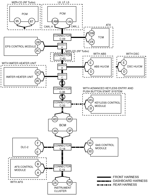
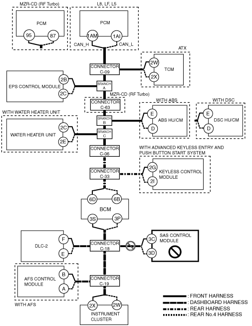
A
Possible cause
System wiring diagram
am6zzw00003963
|
Inspection item
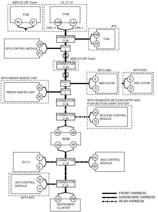
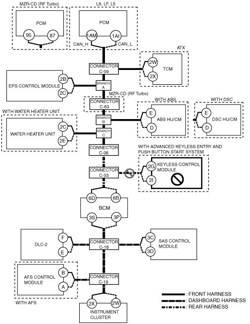
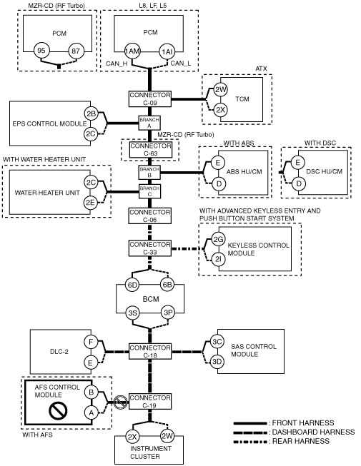
B
Possible cause
System wiring diagram
am6zzw00003964
|
Inspection item
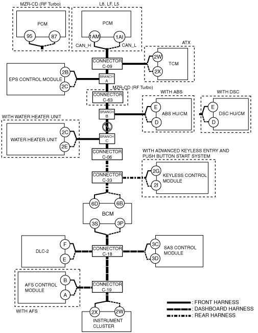
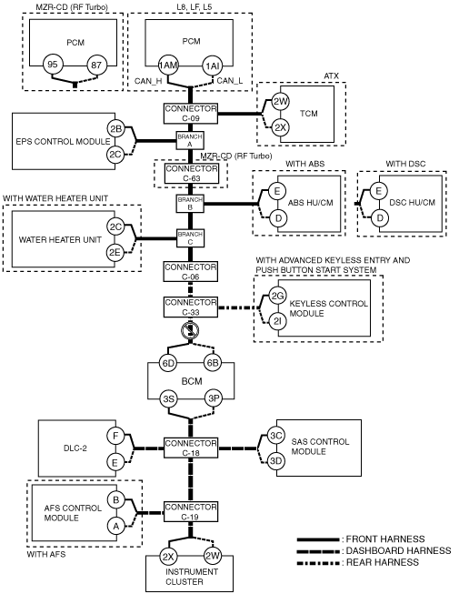
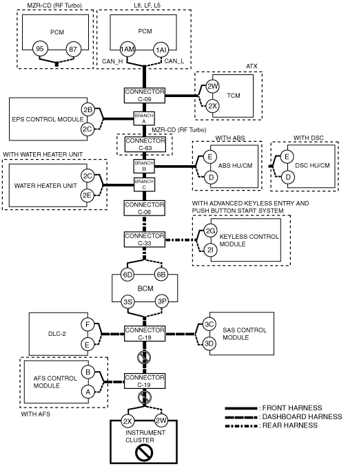
C
Possible cause
System wiring diagram
am6zzw00003965
|
Inspection item
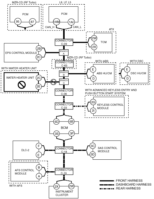
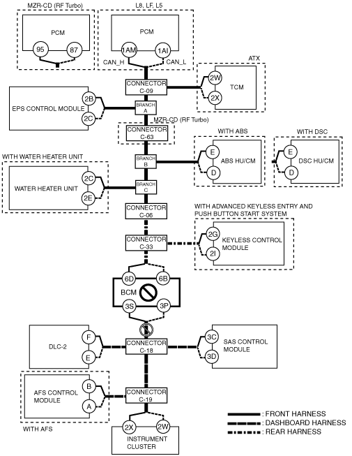
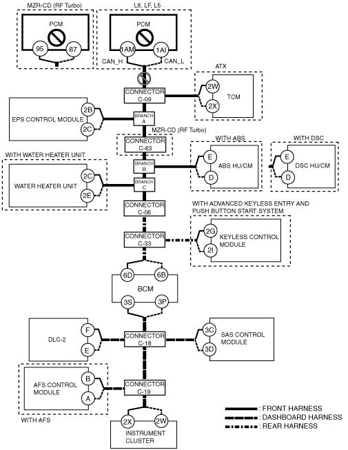
D
Possible cause
System wiring diagram
am6zzw00003966
|
Inspection item
E
Possible cause
System wiring diagram
am6zzw00003967
|
Inspection item
F
Possible cause
System wiring diagram
am6zzw00003968
|
Inspection item
G
Possible cause
System wiring diagram
am6zzw00003969
|
Inspection item
H
Possible cause
System wiring diagram
am6zzw00003970
|
Inspection item
I
Possible cause
System wiring diagram
am6zzw00003971
|
Inspection item
J
Possible cause
System wiring diagram
am6zzw00003972
|
Inspection item
K
Possible cause
System wiring diagram
am6zzw00003973
|
Inspection item
L
Possible cause
System wiring diagram
am6zzw00003974
|
Inspection item
M
Possible cause
System wiring diagram
am6zzw00003975
|
Inspection item
N
Possible cause
System wiring diagram
am6zzw00003976
|
Inspection item
O
Possible cause
System wiring diagram
am6zzw00003977
|
Inspection item