|
am6zzn00000899
ON-BOARD DIAGNOSTIC SYSTEM FUNCTION [AUDIO SYSTEM]
id0920001018a1
Self-diagnostic Function
Malfunction detection function
Memory function
Display function
am6zzn00000899
|
|
Supplier code |
Supplier name |
|---|---|
|
01
|
SANYO Automedia
|
|
02
|
Panasonic
|
|
03
|
Clarion
|
|
04
|
Pioneer
|
|
05
|
VISTEON
|
|
Device code |
Parts name |
|---|---|
|
09
|
Audio unit
|
|
10
|
MP3 applicable CD player
|
|
16
|
CAN system
|
|
17
|
CAN communication line
|
|
21
|
Audio panel
|
|
22
|
MP3 applicable CD changer
|
|
Error code |
Malfunction description |
|---|---|
|
01
|
Internal mechanism error
|
|
02
|
Servo mechanism error
|
|
07
|
Disc reading error
|
|
08
|
Blank media
|
|
10
|
BUS line (communication line) error
|
|
11
|
CAN line (communication line) error
|
|
12
|
CAN line (communication line) error
|
|
17
|
Incorrect Combination
|
|
18
|
Incorrect Combination
|
|
19
|
Communication line
|
|
20
|
Insufficient power supply
|
|
21
|
Amplifier related circuit
|
|
22
|
Tuner error
|
|
Screen display |
Malfunction location |
|
|---|---|---|
|
DTC |
Output signal |
|
|
09: Er20
|
CHECK
BATTERY
|
Power supply circuit to audio unit
|
|
09: Er21
|
CHECK
SPEAKER AND
WIRE
|
• Speaker or speaker circuit
• Audio unit (peripheral circuit for power amplifier)
|
|
09: Er22
|
TUNER
MALFUNCTION
|
Audio unit (peripheral circuit for tuner)
|
|
10: Er01
|
CD-DRIVE
MALFUNCTION
|
MP3 applicable CD player system
|
|
10: Er02
|
CD-DRIVE
MALFUNCTION
|
MP3 applicable CD player system
|
|
10: Er07
|
CHECK
CD-DRIVE AND
DISC
|
MP3 applicable CD player system
|
|
10: Er08
|
—
|
Non-recordable CD
|
|
10: Er10
|
CD-DRIVE
COMMUNI-
CATION Err
|
MP3 applicable CD player communication circuit system
|
|
16: Er11
|
—
|
CAN system
|
|
16: Er12
|
—
|
CAN system
|
|
17: Er11
|
—
|
CAN system
|
|
21: Er17
|
—
|
Audio panel system
|
|
21: Er18
|
—
|
Audio panel system
|
|
21: Er19
|
—
|
Audio panel system
|
|
22: Er01
|
CD-DRIVE
MALFUNCTION
|
MP3 applicable CD changer system
|
|
22: Er02
|
CD-DRIVE
MALFUNCTION
|
MP3 applicable CD changer system
|
|
22: Er07
|
CHECK
CD-DRIVE AND
DISC
|
MP3 applicable CD changer system
|
|
22: Er08
|
—
|
Non-recordable CD
|
|
22: Er10
|
CD-DRIVE
COMMUNI-
CATION Err
|
MP3 applicable CD changer communication circuit system
|
|
no Err
|
—
|
No DTCs stored
|
Diagnostic Assist Function
Switch
am6zzn00000900
|
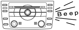
Speaker
Radio
am6zzn00000901
|
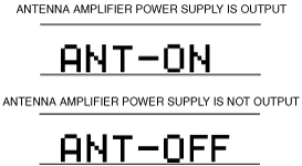
Antenna control condition
am6zzn00000902
|
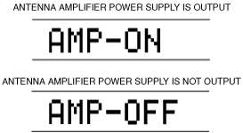
Audio Amplifier control condition
am6zzn00000903
|
Dial switch
am6zzn00000904
|
Audio amplifier specification
am6zzn00000905
|