ON-BOARD DIAGNOSTIC SYSTEM FUNCTION [HANDS-FREE TELEPHONE (HF/TEL) SYSTEM]
id0920001018a8
• The on-board diagnostic system has a self-diagnostic function and diagnostic assist function to help technicians locate malfunctions.
Self-diagnostic Function
Malfunction detection function
-
• The malfunction detection function detects malfunctions occurring in the HF/TEL system.
Memory function
-
• The memory function converts a malfunction detected by the malfunction detection function to a DTC and stores it. The error currently occurring is stored as a present malfunction.Up to three DTCs (with audio unit), or six (with car-navigation unit) can be stored as a present malfunction.The error that has previously occurred is stored as a past malfunction.Up to three DTCs (with audio unit), or six (with car-navigation unit) can be stored as a past malfunction. The DTCs, together with the number of times the ignition switch has been turned off after the occurrence of an error (maximum of 255 times), are stored as a past malfunction.
Display function
-
With audio unit
-
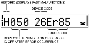
• When the self-diagnostic function is activated, the information display displays the DTC stored in the memory.
• The DTC consists of the following codes and numbers:
-
― Malfunction type
― Number of times the ignition switch has been turned off after the occurrence of an error
― Device code
― Error code
• Refer to the Workshop Manual for the display method.
Current malfunction
Past malfunction
-
With car-navigation unit
-
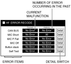
• When the self-diagnostic function is activated, the displays the DTC stored in the memory.
• The DTC consists of the following codes and numbers:
Error history display screen
-
― Error items
― Current malfunction
― Number of times the ignition switch has been turned off after the occurrence of an error
― Detail Switch
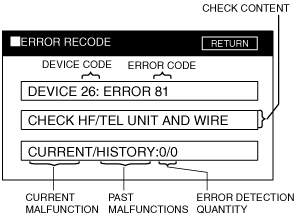
Detail display screen
-
― Device code
― Error code
― Check content
― Number of times present/past malfunction has occurred
• Refer to the Workshop Manual for the display method.
Error history display screen
Detail display screen
DTC table
|
Screen display
|
Inferred cause/verified content
|
|
Car-navigation unit
|
Audio unit
|
|
Device code
|
Error code
|
|
26
|
81
|
26: Er81
|
CAN system
|
|
82
|
26: Er82
|
Short to power supply in wiring harness between microphone (Input signal) and HF/TEL unit
|
|
83
|
26: Er83
|
Short to GND/power supply in microphone power supply circuit
|
|
84
|
26: Er84
|
Any of the following is detected:
• The microphone power supply circuit is not connected.
• Open circuit in the microphone input circuit
• Microphone input circuit short to body ground
|
|
85
|
26: Er85
|
• Poor contact in the hands-free telephone switch or hands-free telephone unit (HF/TEL unit) connector
• Voice recognition/hands-free switch malfunction
|
|
86
|
26: Er86
|
HF/TEL unit malfunction
|
|
No Error
|
no Err
|
DTC is not recorded.
|
Diagnostic Assist Function
With audio unit
-
• The diagnostic assist function displays the operating condition of the following functions (components) and forces them to operate in order to examine whether they are malfunctioning or not.
• For the start procedure of each mode, refer to the Workshop Manual.
-
Software version verification
-
• Displays the software version on the information display.
-
Connection condition verification
-
• Displays the connection status on the information display and examines the HF/TEL system-related unit, wiring harness, and connector.
-
Password reset
-
• Operate the switch and reset the password.
With car-navigation unit
-
• Input a diagnostic assist code and display the unit’s operation conditions, or force the operation to examine the integrity of functions (parts).
• For start-up methods of each mode, refer to the Workshop Manual.
Diagnostic assist code table
|
No.
|
Content/function
|
|
37
|
Connection condition verification
|
|
38
|
Software version verification
|
|
39
|
Password reset
|