 |
am6zzn00001373
ON-BOARD DIAGNOSTIC FUNCTION [CAN (CONTROLLER AREA NETWORK)]
id094000104100
Block Diagram
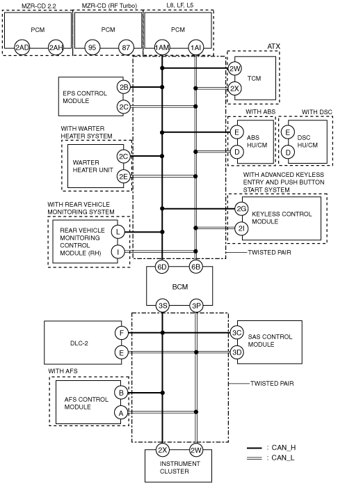
HS-CAN
am6zzn00001373
|
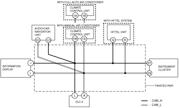
MS-CAN
am6zzn00001374
|
On-Board Diagnostic Function
Malfunction detection function
Fail-safe function
Memory function
Self-malfunction diagnostic function
HS-CAN
|
DTC Output Unit |
DTC |
Malfunction location |
|---|---|---|
|
Instrument cluster
|
U0001:88
|
Module communication error (HS-CAN)
|
|
U0100:00
|
Communication error to PCM
|
|
|
U0100:87
|
Communication error between the instrument cluster and the PCM (no response)
|
|
|
U0101:00
|
Communication error to TCM
|
|
|
U0121:00
|
Communication error to ABS HU/CM (With ABS)
Communication error to DSC HU/CM (With DSC)
|
|
|
U0131:00
|
Communication error to EPS
|
|
|
U0140:00
|
Communication error to BCM
|
|
|
U0151:00
|
Communication error to SAS control module
|
|
|
U0166:00
|
Communication error to water heater unit
|
|
|
U0182:00
|
Communication error to AFS control module
|
|
|
U0214:00
|
Communication error to keyless control module
|
|
|
U0232:00
|
Communication error to rear vehicle monitoring control module (RH)
|
|
|
U0401:68
|
Signal error from PCM
|
|
|
U0402:68
|
Signal error from TCM
|
|
|
U0415:68
|
Signal error from DSC HU/CM (With ABS)
Signal error from DSC HU/CM (With DSC)
|
|
|
U0515:68
|
Signal error from keyless control module
|
|
|
PCM*1
|
U0073:00
|
CAN system communication error
|
|
U0101:00
|
Communication error to TCM
|
|
|
U0121:00
|
Communication error to ABS HU/CM (With ABS)
Communication error to DSC HU/CM (With DSC)
|
|
|
U0131:00
|
Communication error to EPS control module
|
|
|
U0140:00
|
Communication error to BCM
|
|
|
U0151:00
|
Communication error to SAS control module
|
|
|
U0155:00
|
Communication error to instrument cluster
|
|
|
PCM*2
|
U0073:00
|
CAN system communication error
|
|
U0121:00
|
Communication error to ABS HU/CM (With ABS)
Communication error to DSC HU/CM (With DSC)
|
|
|
U0155:00
|
Communication error to instrument cluster
|
|
|
TCM*3
|
U0073:00
|
CAN system communication error
|
|
U0100:00
|
Communication error to PCM
|
|
|
EPS control module
|
U0001:88
|
CAN system communication error
|
|
U0100:00
|
Communication error to PCM
|
|
|
U0401:00
|
Signal error from PCM
|
|
|
ABS HU/CM*4
|
U0001:88
|
CAN system communication error
|
|
U0100:00
|
Communication error to PCM
|
|
|
U0214:00*1
|
Communication error to keyless control module
|
|
|
DSC HU/CM*5
|
U0001:88
|
CAN system communication error
|
|
U0100:00
|
Communication error to PCM
|
|
|
U0101:00
|
Communication error to TCM
|
|
|
U0140:00
|
Communication error to BCM
|
|
|
U0155:00
|
Communication error to instrument cluster
|
|
|
U0214:00*6
|
Communication error to keyless control module
|
|
|
U0401:00
|
Signal error from PCM
|
|
|
U0401:68
|
Signal error from PCM
|
|
|
U0402:00
|
Signal error from TCM
|
|
|
BCM
|
U0001:88
|
Unit communication error (HS-CAN)
|
|
U0100:00
|
Communication error to PCM
|
|
|
U0101:00
|
Communication error to TCM
|
|
|
U0151:00
|
Communication error to SAS control module
|
|
|
U0214:00*6
|
Communication error to keyless control module
|
|
|
U0401:68
|
Signal error from PCM
|
|
|
U0402:68
|
Signal error from TCM
|
|
|
Rear vehicle monitoring control module*7
|
U0001:88
|
CAN system communication error
|
|
U0100:00
|
Communication error to PCM
|
|
|
U0121:00
|
Communication error to DSC HU/CM
|
|
|
U0140:00
|
Communication error to BCM
|
|
|
U0155:00
|
Communication error to instrument cluster
|
|
|
U0401:68
|
Signal error from PCM
|
|
|
U0415:68
|
Signal error from DSC HU/CM
|
|
|
SAS control module
|
U0001:88
|
CAN system communication error
|
|
U0155:00
|
Communication error to instrument cluster
|
|
|
Water heater unit*8
|
U0001:88
|
CAN system communication error
|
|
U0100:00
|
Communication error to PCM
|
|
|
U0140:00
|
Communication error to BCM
|
|
|
U0155:00
|
Communication error to instrument cluster
|
|
|
Keyless control module*6
|
U0001:88
|
Unit communication error (HS-CAN)
|
|
U0100:00
|
Communication error to PCM
|
|
|
U0101:00
|
Communication error to TCM
|
|
|
U0121:00
|
Communication error to ABS HU/CM (with ABS)
Communication error to DSC HU/CM (with DSC)
|
|
|
U0401:68
|
Signal error from PCM
|
MS-CAN
|
DTC Output Unit |
DTC |
Malfunction location |
|---|---|---|
|
Instrument cluster
|
U0010:88
|
Module communication error (MS-CAN)
|
|
U0164:00
|
Communication error to climate control unit
|
|
|
Information display
|
U0001088
|
Module communication error (MS-CAN)
|
|
U015500HEC
|
Communication error to instrument cluster
|
|
|
U016400EATC
|
Communication error to climate control unit
|
|
|
U018400ACU
|
Communication error to audio unit
|
|
|
Audio unit (with audio system)
|
16:Er11
|
CAN system communication error
|
|
16:Er12
|
CAN system communication error
|
|
|
17:Er11
|
Communication error to instrument cluster
|
|
|
Car-navigation unit (with car-navigation system)
|
Device code 16:Error code 12
|
CAN system communication error
|
|
Device code 17:Error code 11
|
Communication error to instrument cluster
|
|
|
Climate control unit
|
U0010:88
|
CAN system communication error
|
|
U0155:00
|
Communication error to instrument cluster
|
|
|
U0184:00
|
Communication error to audio unit/car-navigation unit
|
|
|
U0423:68
|
Invalid date received from Instrument cluster
|
|
|
HF/TEL unit (with audio system)
|
26:Er81
|
CAN system communication error
|
|
HF/TEL unit (with car-navigation system)
|
Device code 26:Error code 81
|
CAN system communication error
|
Narrowing down malfunction locations
Troubleshooting procedure
am6zzn00001410
|
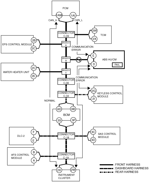
Example (L8, LF, L5): ABS HU/CM-related wiring harness open circuit (if DTC is output)
1. Verify the CAN system-related module DTCs and the failed module using the Mazda Modular Diagnostic System (M-MDS).
|
Module |
Displayed DTC |
Probable malfunction location |
|---|---|---|
|
PCM
|
U0121:00
|
Communication error to ABS/TCS HU/CM
|
|
Keyless control module
|
U0121:00
|
Communication error to ABS/TCS HU/CM
|
|
Instrument cluster
|
U0121:00
|
Communication error to ABS/TCS HU/CM
|
|
Module |
Fail |
|---|---|
|
ABS HU/CM
|
×
|
am6zzn00001375
|
2. Despite normal communication between the PCM and instrument cluster, a communication error DTC is displayed for the signal between the ABS HU/CM and PCM/keyless control module/Instrument cluster. In addition, the wiring harness between the ABS HU/CM and branch B or the ABS HU/CM is considered to be malfunctioning because “Fail” is displayed for the ABS HU/CM.
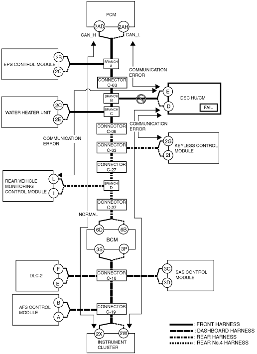
Example (MZR-CD 2.2): DSC HU/CM-related wiring harness open circuit (if DTC is output)
1. Verify the CAN system-related module DTCs and the failed module using the Mazda Modular Diagnostic System (M-MDS).
|
Module |
Displayed DTC |
Probable malfunction location |
|---|---|---|
|
PCM
|
U0121:00
|
Communication error to DSC HU/CM
|
|
Rear vehicle monitoring control module
|
U0121:00
|
Communication error to DSC HU/CM
|
|
Keyless control module
|
U0121:00
|
Communication error to DSC HU/CM
|
|
Instrument cluster
|
U0121:00
|
Communication error to DSC HU/CM
|
|
Module |
Fail |
|---|---|
|
DSC HU/CM
|
×
|
am6zzn00001376
|
2. The wiring harness between the DSC HU/CM and branch B, or the DSC HU/CM itself could have a malfunction because DTCs are displayed indicating a communication error between the DSC HU/CM and PCM/keyless control module/rear vehicle monitoring control module/instrument cluster, in addition to “Fail” on the DSC HU/CM, even though communication between the PCM and the instrument cluster is normal.