|
b13bje00000003
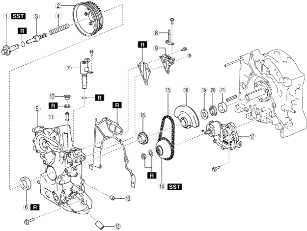
HOUSING DISASSEMBLY (II)
id011000130500
1. Disassemble in the order indicated in the table.
Type A
b13bje00000003
|
|
1
|
Pulley lockbolt
|
|
2
|
Pulley component
|
|
3
|
Eccentric shaft bypass valve
|
|
4
|
Spring
|
|
5
|
Front cover
(See Front Cover Disassembly Note.)
|
|
6
|
Front oil seal
|
|
7
|
Plug
|
|
8
|
Control valve spring
|
|
9
|
Control valve
|
|
10
|
Metering oil pump drive gear
|
|
11
|
Oil pump sprocket wheel
|
|
12
|
Oil pump chain
|
|
13
|
Oil pump drive gear
|
|
14
|
Oil pump component
|
|
15
|
Balance weight
|
|
16
|
Thrust plate
|
|
17
|
Needle bearing
|
|
18
|
Spacer
|
|
19
|
Rear outer rotor
|
|
20
|
Rear inner rotor
|
|
21
|
Middle plate
|
|
22
|
Front outer rotor
|
|
23
|
Front inner rotor
|
|
24
|
Shaft
|
|
25
|
Oil pump body
|
|
26
|
Snap ring
|
|
27
|
Driven gear
|
|
28
|
Pin
|
|
29
|
Driven shaft
|
Type B
be13ze00000009
|
|
1
|
Pulley lockbolt
|
|
2
|
Pulley component
|
|
3
|
Eccentric shaft bypass valve
|
|
4
|
Spring
|
|
5
|
Front cover
(See Front Cover Disassembly Note.)
|
|
6
|
Front oil seal
|
|
7
|
OCV
|
|
8
|
Oil pipe
|
|
9
|
OCV case
|
|
10
|
Plug
|
|
11
|
OCV oil filter
|
|
12
|
Oil filter joint
|
|
13
|
Plug
|
|
14
|
Oil pump sprocket wheel
|
|
15
|
Oil pump chain
|
|
16
|
Oil pump drive gear
|
|
17
|
Oil pump component
|
|
18
|
Balance weight
|
|
19
|
Thrust plate
|
|
20
|
Needle bearing
|
|
21
|
Spacer
|
Pulley Lockbolt Disassembly Note
1. Lock the flywheel (MT) or counterweight (AT) against rotation using the SST.
be13ze00000010
|
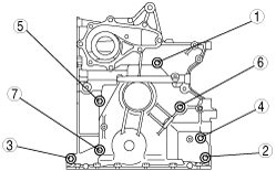
Front Cover Disassembly Note
1. Loosen the engine front cover installation bolts in the order shown in the figure.
be13ze00000011
|
Oil Pump Sprocket Disassembly Note
1. Lock the flywheel (MT) or counterweight (AT) against rotation using the SST.
be13ze00000010
|
2. Unlock the crimped part of the lock washer and remove the locknut and lock washer.
3. Remove the oil pump drive gear and oil pump sprocket wheel with the oil pump chain engaged.
be13ze00000012
|