 |
be13ze00000027
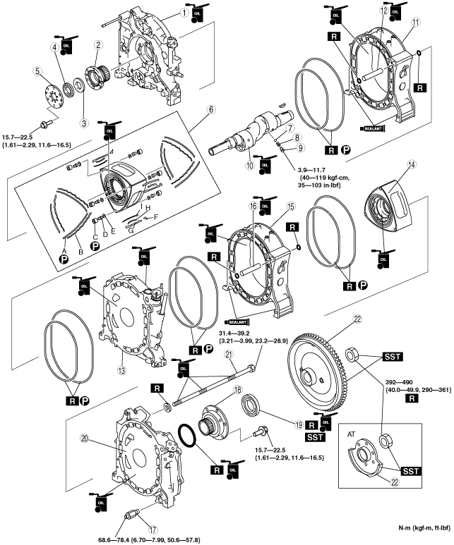
HOUSING ASSEMBLY (I)
id011000136000
1. Assemble in the order indicated in the table.
be13ze00000027
|
|
1
|
Front housing
|
|
2
|
Front stationary gear
|
|
3
|
Thrust plate
(See Thrust Plate Assembly Note.)
|
|
4
|
Needle bearing
|
|
5
|
Plate
|
|
6
|
Front rotor
A: Side seal
B: Side seal spring
C: Corner seal
D: Corner seal plug
E: Corner seal spring
F: Side piece
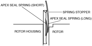
G: Apex seal
H: Apex seal spring (short)
I: Apex seal spring (long)
(See Rotor Assembly Note.)
|
|
7
|
Steel ball
|
|
8
|
Spring
|
|
9
|
Oil jet plug
(See Oil Jet Plug Assembly Note.)
|
|
10
|
Eccentric shaft
|
|
11
|
Front rotor housing
(See Rotor Housing Assembly Note.)
|
|
12
|
Tubular dowel (front rotor housing side)
|
|
13
|
Intermediate housing
|
|
14
|
Rear rotor
(See Rotor Assembly Note.)
|
|
15
|
Rear rotor housing
(See Rotor Housing Assembly Note.)
|
|
16
|
Tubular dowel (rear rotor housing side)
|
|
17
|
Pressure regulator (Type A)
|
|
18
|
Rear stationary gear
|
|
19
|
Rear oil seal
(See Rear Oil Seal Assembly Note.)
|
|
20
|
Rear housing
(See Rear Housing Assembly Note.)
|
|
21
|
Tension bolt
(See Tension Bolt Assembly Note.)
|
|
22
|
Flywheel (MT), counterweight (AT)
|
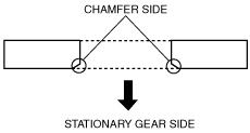
Thrust Plate Assembly Note
1. Place the chamfer side facing the stationary gear.
be13ze00000028
|
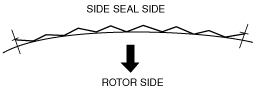
Rotor Assembly Note
1. Assemble the side seal spring in the direction shown in the figure.
be13ze00000029
|
2. Assemble the side seal spring in the direction shown in the figure.
be13ze00000030
|
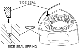
3. Apply petroleum jelly between the side seal and side seal groove.
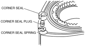
4. Assemble the corner seal plug to the corner seal.
be13ze00000031
|
be13ze00000032
|
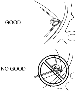
5. Assemble the corner seal and corner seal spring with the notch aligned with the apex seal groove.
6. Apply petroleum jelly between the corner seal and corner seal groove.
7. Place the rotor in the housing.
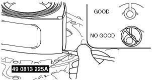
8. Insert the SST into the apex seal groove of the rotor and verify that the apex seal groove of the corner seal is aligned with the apex seal groove of the rotor.
be13ze00000033
|
9. Assemble the side seal and corner seal for the engine rear side in the same way as the engine front side.
Oil Jet Plug Assembly Note
1. Apply thread locking compound to the threads of the oil jet plug.
2. Install the oil jet plug.
Rotor Housing Assembly Note
1. Apply petroleum jelly to a new seal rubber.
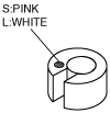
2. Assemble the outer seal rubber to the housing with the white paint in the direction shown in the figure.
be13ze00000034
|
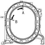
3. Assemble the inner seal rubber to the housing with the seal rubber joint placed between A—B.
be13ze00000035
|
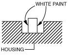
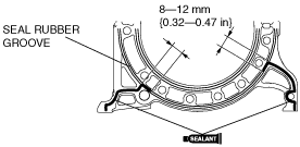
4. Apply the silicone sealant to the position indicated in the figure.
be13ze00000036
|
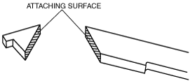
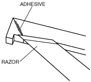
5. Apply thread locking compound to the attaching surface of the apex seal and the side piece and affix them.
be13ze00000037
|
be13ze00000038
|
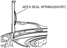
6. Assemble the apex seal and apex seal spring (short) together with the side piece to the engine rear side.
be13ze00000039
|
7. Assemble the apex seal spring (long) while pressing the apex seal spring (short).
be13ze00000040
|
Intermediate Housing Assembly Note
be13ze00000041
|
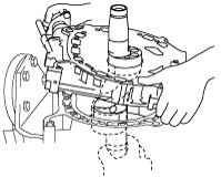
1. Assemble the intermediate housing with the support of an assistant pushing the eccentric shaft up approx. 3 cm {1.18 in}.
be13ze00000042
|
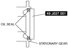
Rear Oil Seal Assembly Note
1. Assemble the oil seal using the SST.
be13ze00000043
|
Rear Housing Assembly Note
1. Assemble the rear housing with the rear stationary gear and the internal gear of the rotor engaged.
be13ze00000041
|
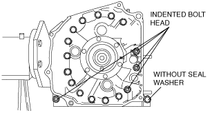
Tension Bolt Assembly Note
1. Apply engine oil to the tension bolt threads and assemble to the housing with a new seal washer.
be13ze00000044
|
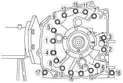
2. Tighten the tension bolts in the order indicated in the figure in 2—3 passes.
be13ze00000045
|
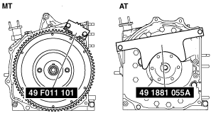
Flywheel (MT), Counterweight (AT) Assembly Note
1. Lock the flywheel (MT) or counterweight (AT) against rotation using the SSTs.
be13ze00000046
|
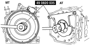
2. Tighten the locknut using the SST.
be13ze00000047
|