 |
be13ze00000013
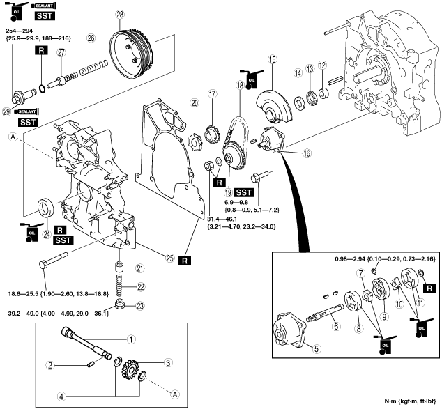
HOUSING ASSEMBLY (II)
id011000136300
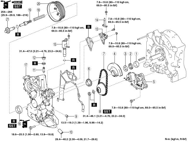
1. Assemble in the order indicated in the table.
Type A
be13ze00000013
|
|
1
|
Driven shaft
|
|
2
|
Pin
|
|
3
|
Driven gear
|
|
4
|
Snap ring
|
|
5
|
Oil pump body
|
|
6
|
Shaft
|
|
7
|
Front inner rotor
|
|
8
|
Front outer rotor
|
|
9
|
Middle plate
|
|
10
|
Rear inner rotor
|
|
11
|
Rear outer rotor
|
|
12
|
Spacer
(See Spacer Assembly Note.)
|
|
13
|
Needle bearing
|
|
14
|
Thrust plate
|
|
15
|
Balance weight
|
|
16
|
Oil pump component
|
|
17
|
Oil pump drive gear
|
|
18
|
Oil pump chain
|
|
19
|
Oil pump sprocket wheel
|
|
20
|
Metering oil pump drive gear
|
|
21
|
Control valve
|
|
22
|
Control valve spring
|
|
23
|
Plug
|
|
24
|
Front oil seal
(See Front Oil Seal Assembly Note.)
|
|
25
|
Front cover
(See Front Cover Assembly Note.)
|
|
26
|
Spring
|
|
27
|
Eccentric shaft bypass valve
|
|
28
|
Pulley component
|
|
29
|
Pulley lockbolt
|
Type B
be13ze00000014
|
|
1
|
Spacer
(See Spacer Assembly Note.)
|
|
2
|
Needle bearing
|
|
3
|
Thrust plate
|
|
4
|
Balance weight
|
|
5
|
Oil pump component
|
|
6
|
Oil pump drive gear
|
|
7
|
Oil pump chain
|
|
8
|
Oil pump sprocket wheel
|
|
9
|
Plug
|
|
10
|
Oil filter joint
|
|
11
|
OCV oil filter
|
|
12
|
Plug
|
|
13
|
OCV case
|
|
14
|
Oil pipe
|
|
15
|
OCV
|
|
16
|
Front oil seal
(See Front Oil Seal Assembly Note.)
|
|
17
|
Front cover
(See Front Cover Assembly Note.)
|
|
18
|
Spring
|
|
19
|
Eccentric shaft bypass valve
|
|
20
|
Pulley component
|
|
21
|
Pulley lockbolt
|
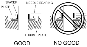
Spacer Assembly Note
be13ze00000015
|
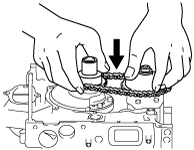
Oil Pump Drive Gear Assembly Note
1. Assemble the oil pump drive gear or oil pump sprocket wheel with the oil pump chain engaged.
be13ze00000016
|
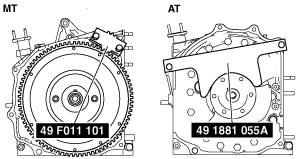
Oil Pump Sprocket Wheel Assembly Note
1. Lock the flywheel (MT) and counterweight (AT) against rotation using the SSTs.
be13ze00000017
|
2. Assemble the oil pump shaft with a new lock washer and locknut, and tighten.
3. Bend the lock washer and crimp.
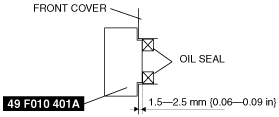
Front Oil Seal Assembly Note
1. Press the oil seal in using the SST.
be13ze00000018
|
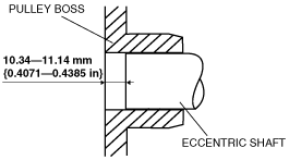
Front Cover Assembly Note
1. Before installing the front cover, install the pulley boss to the eccentric shaft and measure the height between the eccentric shaft top and the pulley boss.
be13ze00000019
|
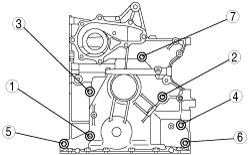
2. Tighten the engine front cover installation bolts in the order shown in the figure.
be13ze00000020
|
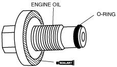
Pulley Lockbolt Assembly Note
1. Lock the flywheel (MT) or counterweight (AT) against rotation using the SSTs.
be13ze00000017
|
2. Apply engine oil to the pulley lockbolt threads.
be13ze00000021
|
3. Assemble a new O-ring.
4. Apply silicone sealant to the seating face.
5. Tighten the pulley lockbolt.