 |
ar8wzn00000497
ON-BOARD DIAGNOSTIC SYSTEM TEST MODE [13B-MSP]
id0102g1142500
|
Diagnostic test mode |
Item |
|---|---|
|
Mode 01
|
Sending diagnostic data (PID data monitor/On-board system readiness test)
|
|
Mode 02
|
Sending freeze frame data
|
|
Mode 03
|
Sending emission-related malfunction code (DTC)
|
|
Mode 04
|
Clearing/resetting emission-related malfunction information
|
|
Mode 07
|
Sending continuous monitoring system test results (pending code)
|
|
Mode 09
|
Request vehicle information
|
Sending Diagnostic Data
PID data monitor
PID data monitor table
|
Full names |
Unit |
|
|---|---|---|
|
Monitor status since DTCs cleared
|
–
|
|
|
Fuel system loop status
|
Refer to list below.
|
|
|
LOAD
|
%
|
|
|
ECT
|
°C
|
°F
|
|
Short term fuel trim
|
%
|
|
|
Long term fuel trim
|
%
|
|
|
Engine speed
|
rpm
|
|
|
Vehicle speed
|
km/h
|
mph
|
|
Spark advance
|
°
|
|
|
IAT
|
°C
|
°F
|
|
MAF
|
g/s
|
|
|
Absolute TP
|
%
|
|
|
AIR control status
|
–
|
|
|
A/F sensor, HO2S location
|
–
|
|
|
HO2S output
|
V
|
|
|
%
|
||
|
OBD requirement according to vehicle design
|
–
|
|
|
Time since engine start
|
s
|
|
|
Distance travelled while MIL is activated
|
km
|
mile
|
|
Purge solenoid valve control signal
|
%
|
|
|
Fuel tank level
|
%
|
|
|
Number of warm-ups since DTCs cleared
|
–
|
|
|
Distance travelled since DTCs cleared
|
km
|
mile
|
|
BARO
|
kPa
|
|
|
Lambda
|
–
|
|
|
A/F sensor output current
|
mA
|
|
|
Estimated catalyst converter temperature
|
°C
|
°F
|
|
Monitor status this driving cycle
|
–
|
|
|
PCM power supply voltage
|
V
|
|
|
Absolute load value
|
%
|
|
|
Relative TP
|
%
|
|
|
Ambient air temperature
|
°C
|
°F
|
|
TP from TP sensor No.2
|
%
|
|
|
APP from APP sensor No.1
|
%
|
|
|
APP from APP sensor No.2
|
%
|
|
|
Throttle actuator control signal
|
%
|
|
On-board system readiness test
Sending Freeze Frame Data
Freeze Frame Data monitor table
|
Full names |
Unit |
|
|---|---|---|
|
DTC that caused required Freeze Frame Data storage
|
–
|
|
|
Fuel system loop status
|
Refer to list below.
|
|
|
LOAD
|
%
|
|
|
ECT
|
°C
|
°F
|
|
Short term fuel trim
|
%
|
|
|
Long term fuel trim
|
%
|
|
|
Engine speed
|
rpm
|
|
|
Vehicle speed
|
km/h
|
mph
|
|
Spark advance
|
°
|
|
|
IAT
|
°C
|
°F
|
|
MAF
|
g/s
|
|
|
Absolute TP
|
%
|
|
|
AIR control status
|
–
|
|
|
HO2S output
|
V
|
|
|
%
|
||
|
Time since engine start
|
s
|
|
|
Purge solenoid valve control signal
|
%
|
|
|
Fuel tank level
|
%
|
|
|
Number of warm-ups since DTCs cleared
|
–
|
|
|
Distance travelled since DTCs cleared
|
km
|
mile
|
|
BARO
|
kPa
|
|
|
Estimated catalyst converter temperature
|
°C
|
°F
|
|
PCM power supply voltage
|
V
|
|
|
Lambda
|
–
|
|
|
Absolute load value
|
%
|
|
|
Relative TP
|
%
|
|
|
Ambient air temperature
|
°C
|
°F
|
|
TP from TP sensor No.2
|
%
|
|
|
APP from APP sensor No.1
|
%
|
|
|
APP from APP sensor No.2
|
%
|
|
|
Throttle actuator control signal
|
%
|
|
Sending Emission-related Malfunction Code
DTC Table
|
DTC No. |
Condition |
MIL |
Generator warning light |
DC |
Monitor item |
Memory function |
|---|---|---|---|---|---|---|
|
B1342
|
PCM malfunction
|
OFF
|
—
|
—
|
—
|
—
|
|
P0030
|
A/F sensor heater control circuit problem
|
ON
|
—
|
2
|
A/F sensor heater, HO2S heater
|
×
|
|
P0031
|
A/F sensor heater control circuit low input
|
ON
|
—
|
2
|
A/F sensor heater, HO2S heater
|
×
|
|
P0032
|
A/F sensor heater control circuit high input
|
ON
|
—
|
2
|
A/F sensor heater, HO2S heater
|
×
|
|
P0037
|
HO2S heater control circuit low input
|
ON
|
—
|
2
|
A/F sensor heater, HO2S heater
|
×
|
|
P0038
|
HO2S heater control circuit high input
|
ON
|
—
|
2
|
A/F sensor heater, HO2S heater
|
×
|
|
P0076*1
|
VDI solenoid valve control circuit low input
|
OFF
|
—
|
2
|
Other
|
×
|
|
P0077*1
|
VDI solenoid valve control circuit high input
|
OFF
|
—
|
2
|
Other
|
×
|
|
P0101
|
MAF sensor circuit range/performance problem
|
ON
|
—
|
2
|
CCM
|
×
|
|
P0102
|
MAF sensor circuit low input
|
ON
|
—
|
1
|
CCM
|
×
|
|
P0103
|
MAF sensor circuit high input
|
ON
|
—
|
1
|
CCM
|
×
|
|
P0107
|
BARO sensor circuit low input
|
ON
|
—
|
1
|
CCM
|
×
|
|
P0108
|
BARO sensor circuit high input
|
ON
|
—
|
1
|
CCM
|
×
|
|
P0112
|
IAT sensor circuit low input
|
ON
|
ON
|
1
|
CCM
|
×
|
|
P0113
|
IAT sensor circuit high input
|
ON
|
ON
|
1
|
CCM
|
×
|
|
P0117
|
ECT sensor circuit low input
|
ON
|
—
|
1
|
CCM
|
×
|
|
P0118
|
ECT sensor circuit high input
|
ON
|
—
|
1
|
CCM
|
×
|
|
P0122
|
TP sensor No.1 circuit low input
|
ON
|
—
|
1
|
CCM
|
×
|
|
P0123
|
TP sensor No.1 circuit high input
|
ON
|
—
|
1
|
CCM
|
×
|
|
P0130
|
A/F sensor circuit problem
|
ON
|
—
|
2
|
A/F sensor, HO2S
|
×
|
|
P0131
|
A/F sensor circuit low input
|
ON
|
—
|
2
|
A/F sensor, HO2S
|
×
|
|
P0132
|
A/F sensor circuit high input
|
ON
|
—
|
2
|
A/F sensor, HO2S
|
×
|
|
P0133
|
A/F sensor circuit slow response
|
ON
|
—
|
2
|
A/F sensor, HO2S
|
×
|
|
P0137
|
HO2S circuit low input
|
ON
|
—
|
2
|
A/F sensor, HO2S
|
×
|
|
P0138
|
HO2S circuit high input
|
ON
|
—
|
2
|
A/F sensor, HO2S
|
×
|
|
P0139
|
HO2S circuit slow response
|
ON
|
—
|
2
|
A/F sensor, HO2S
|
×
|
|
P0171
|
System too lean
|
ON
|
—
|
2
|
Fuel system
|
×
|
|
P0172
|
System too rich
|
ON
|
—
|
2
|
Fuel system
|
×
|
|
P0222
|
TP sensor No.2 circuit low input
|
ON
|
—
|
1
|
CCM
|
×
|
|
P0223
|
TP sensor No.2 circuit high input
|
ON
|
—
|
1
|
CCM
|
×
|
|
P0300
|
Random misfire detected
|
Flash/ON
|
—
|
1 or 2
|
Misfire
|
×
|
|
P0301
|
Front rotor misfire detected
|
Flash/ON
|
—
|
1 or 2
|
Misfire
|
×
|
|
P0302
|
Rear rotor misfire detected
|
Flash/ON
|
—
|
1 or 2
|
Misfire
|
×
|
|
P0327
|
KS No.1 circuit low input
|
ON
|
—
|
1
|
CCM
|
×
|
|
P0328
|
KS No.1 circuit high input
|
ON
|
—
|
1
|
CCM
|
×
|
|
P0332
|
KS No.2 circuit low input
|
ON
|
—
|
1
|
CCM
|
×
|
|
P0333
|
KS No.2 circuit high input
|
ON
|
—
|
1
|
CCM
|
×
|
|
P0335
|
Eccentric shaft position sensor circuit problem
|
ON
|
—
|
1
|
CCM
|
×
|
|
P0336
|
Eccentric shaft position sensor circuit range/performance problem
|
ON
|
—
|
1
|
CCM
|
×
|
|
P0410
|
Secondary air injection system problem
|
ON
|
—
|
2
|
AIR system
|
×
|
|
P0420
|
Catalyst system efficiency below threshold
|
ON
|
—
|
2
|
Catalyst
|
×
|
|
P0443
|
Purge solenoid valve circuit problem
|
ON
|
—
|
2
|
CCM
|
×
|
|
P0480
|
Cooling fan relay No.1 control circuit problem
|
OFF
|
—
|
2
|
Other
|
×
|
|
P0481
|
Cooling fan relay No.2 and No.3 control circuit problem
|
OFF
|
—
|
2
|
Other
|
×
|
|
P0482
|
Cooling fan relay No.4 and No.5 control circuit problem
|
OFF
|
—
|
2
|
Other
|
×
|
|
P0500
|
VSS circuit problem
|
ON
|
—
|
2
|
CCM
|
×
|
|
P0505
|
Idle air control system problem
|
OFF
|
—
|
—
|
—
|
—
|
|
P0522
|
Oil pressure sensor circuit low input
|
OFF
|
—
|
1
|
Other
|
×
|
|
P0523
|
Oil pressure sensor circuit high input
|
OFF
|
—
|
1
|
Other
|
×
|
|
P0562
|
System voltage low (KAM)
|
ON
|
—
|
1
|
CCM
|
×
|
|
P0564*2
|
Cruise control switch input circuit problem
|
OFF
|
—
|
1
|
Other
|
×
|
|
P0571*2
|
Brake switch No.2 input circuit problem
|
OFF
|
—
|
1
|
Other
|
×
|
|
P0601
|
PCM memory check sum error
|
ON
|
—
|
1
|
CCM
|
×
|
|
P0602
|
PCM programming error
|
ON
|
—
|
1
|
CCM
|
×
|
|
P0604
|
PCM random access memory error
|
ON
|
—
|
1
|
CCM
|
×
|
|
P0606
|
PCM processor error
|
ON
|
—
|
1
|
CCM
|
×
|
|
P0610
|
PCM vehicle options error
|
ON
|
—
|
1
|
CCM
|
×
|
|
P0638
|
Throttle actuator control circuit range/performance problem
|
ON
|
—
|
1
|
CCM
|
×
|
|
P0661
|
SSV solenoid valve control circuit low
|
ON
|
—
|
2
|
CCM
|
×
|
|
P0662
|
SSV solenoid valve control circuit high
|
ON
|
—
|
2
|
CCM
|
×
|
|
P0703
|
Brake switch No.1 input circuit problem
|
ON
|
—
|
2
|
CCM
|
×
|
|
P0704*3
|
CPP switch input circuit problem
|
ON
|
—
|
2
|
CCM
|
×
|
|
P0850*3
|
Neutral switch input circuit problem
|
ON
|
—
|
2
|
CCM
|
×
|
|
P1260
|
Immobilizer system problem
|
OFF
|
—
|
1
|
Other
|
—
|
|
P1680
|
OCV circuit low input
|
OFF *4
|
—
|
1
|
Other
|
×
|
|
P1681
|
OCV circuit high input
|
OFF *4
|
—
|
1
|
Other
|
×
|
|
P1682
|
Metering oil pump No.1 circuit low input
|
OFF *4
|
—
|
1
|
Other
|
×
|
|
P1683
|
Metering oil pump No.1 circuit high input
|
OFF *4
|
—
|
1
|
Other
|
×
|
|
P1684
|
Metering oil pump oil pressure sensor –oil pressure is low
|
OFF *4
|
—
|
1
|
Other
|
×
|
|
P1685
|
Metering oil pump oil pressure sensor –oil pressure is high
|
OFF *4
|
—
|
1
|
Other
|
×
|
|
P1686
|
Metering oil pump No.2 circuit low input
|
OFF *4
|
—
|
1
|
Other
|
×
|
|
P1687
|
Metering oil pump No.2 circuit high input
|
OFF *4
|
—
|
1
|
Other
|
×
|
|
P2009
|
APV motor control circuit low input
|
ON
|
—
|
2
|
CCM
|
×
|
|
P2010
|
APV motor control circuit high input
|
ON
|
—
|
2
|
CCM
|
×
|
|
P2096
|
Target A/F feedback system too lean
|
ON
|
—
|
2
|
Fuel system
|
×
|
|
P2097
|
Target A/F feedback system too rich
|
ON
|
—
|
2
|
Fuel system
|
×
|
|
P2101
|
Throttle actuator circuit range/performance
|
ON
|
—
|
1
|
CCM
|
×
|
|
P2107
|
Throttle actuator control module processor error
|
ON
|
—
|
1
|
CCM
|
×
|
|
P2108
|
Throttle actuator control module performance error
|
ON
|
—
|
1
|
CCM
|
×
|
|
P2109
|
TP sensor minimum stop range/performance problem
|
ON
|
—
|
1
|
CCM
|
×
|
|
P2112
|
Throttle actuator control system range/performance problem
|
ON
|
—
|
1
|
CCM
|
×
|
|
P2119
|
Throttle actuator control throttle body range/performance problem
|
ON
|
—
|
2
|
CCM
|
×
|
|
P2122
|
APP sensor No.1 circuit low input
|
ON
|
—
|
1
|
CCM
|
×
|
|
P2123
|
APP sensor No.1 circuit high input
|
ON
|
—
|
1
|
CCM
|
×
|
|
P2127
|
APP sensor No.2 circuit low input
|
ON
|
—
|
1
|
CCM
|
×
|
|
P2128
|
APP sensor No.2 circuit high input
|
ON
|
—
|
1
|
CCM
|
×
|
|
P2135
|
TP sensor No.1/No.2 voltage correlation problem
|
ON
|
—
|
1
|
CCM
|
×
|
|
P2138
|
APP sensor No.1/No.2 voltage correlation problem
|
ON
|
—
|
1
|
CCM
|
×
|
|
P2195
|
A/F sensor signal stuck lean
|
ON
|
—
|
2
|
A/F sensor, HO2S
|
×
|
|
P2196
|
A/F sensor signal stuck rich
|
ON
|
—
|
2
|
A/F sensor, HO2S
|
×
|
|
P2257
|
AIR pump relay control circuit low
|
ON
|
—
|
2
|
AIR system
|
×
|
|
P2258
|
AIR pump relay control circuit high
|
ON
|
—
|
2
|
AIR system
|
×
|
|
P2259
|
AIR solenoid valve control circuit low
|
ON
|
—
|
2
|
AIR system
|
×
|
|
P2260
|
AIR solenoid valve control circuit high
|
ON
|
—
|
2
|
AIR system
|
×
|
|
P2270
|
HO2S signal stuck lean
|
ON
|
—
|
2
|
A/F sensor, HO2S
|
×
|
|
P2271
|
HO2S signal stuck rich
|
ON
|
—
|
2
|
A/F sensor, HO2S
|
×
|
|
P2299*5
|
Accelerator pedal: spring back malfunction
|
—
|
—
|
1
|
Other
|
×
|
|
P2502
|
Charging system voltage problem
|
OFF
|
ON
|
1
|
Other
|
×
|
|
P2503
|
Charging system voltage low
|
OFF
|
ON
|
1
|
Other
|
×
|
|
P2504
|
Charging system voltage high
|
OFF
|
ON
|
1
|
Other
|
×
|
Sending Continuous Monitoring System Test Results
1-drive cycle type
2-drive cycle type
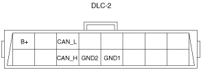
DLC-2 Outline
ar8wzn00000497
|
|
Terminal name |
Function |
|---|---|
|
B+
|
Battery positive voltage
|
|
CAN_H
|
CAN communication line
|
|
CAN_L
|
CAN communication line
|
|
GND1
|
Ground (chassis)
|
|
GND2
|
Ground (signal)
|