 |
ar8uun00000341
ELECTRICAL FAN CONTROL OPERATION [13B-MSP]
id0140g1104000
Operation condition
|
Function |
Cooling fan motor |
Cooling fan relay |
Operation condition |
|||
|---|---|---|---|---|---|---|
|
No.1 |
No.2 |
No.1 |
No.2/No.3 |
No.4/No.5 |
||
|
Regular driving cooling
|
Stop
|
Stop
|
OFF
|
OFF
|
OFF
|
• ECT less than 97 °C {207 °F} and A/C switch OFF
|
|
Low speed rotation
|
Low speed rotation
|
ON
|
OFF
|
OFF
|
• ECT less than 97 °C {207 °F} and A/C switch ON (Refrigerant pressure switch OFF)
• ECT is 97—101 °C {207—213 °F} and Refrigerant pressure switch OFF
|
|
|
Middle speed rotation
|
Middle speed rotation
|
ON
|
ON
|
OFF
|
• ECT is 101—108 °C {214—226 °F}
• ECT less than 101 °C {214 °F} and Refrigerant pressure switch ON
• ECT or above 108 °C {226 °F} and A/C switch ON (Refrigerant pressure switch OFF)
|
|
|
High speed rotation
|
High speed rotation
|
ON
|
ON
|
ON
|
• ECT or above 108 °C {226 °F} and A/C switch OFF
• ECT or above 108 °C {226 °F} and Refrigerant pressure switch ON
|
|
|
After cooling
|
Middle speed rotation
|
Middle speed rotation
|
ON
|
ON
|
OFF
|
• When all the following conditions are met:
|
|
Forced drive
|
High speed rotation
|
High speed rotation
|
ON
|
ON
|
ON
|
• During test mode (during test mode with M-MDS) when the AP is depressed.
|
|
Fail safe
|
High speed rotation
|
High speed rotation
|
ON
|
ON
|
ON
|
• When a failure occurs in the ECT sensor.
|
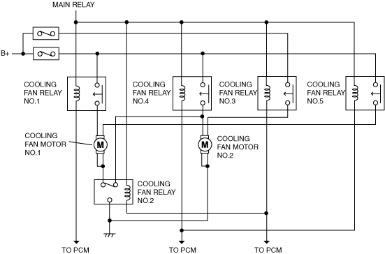
Wiring diagram
ar8uun00000341
|