 |
am6zzw00000123
PCM INSPECTION [13B-MSP]
id0140g1802500
Without Using the SST
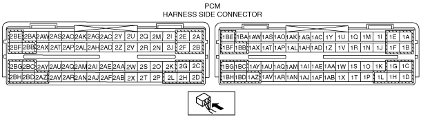
1. Measure the voltage at each terminal.
Terminal voltage table (Reference)
am6zzw00000123
|
|
Terminal |
Signal |
Connected to |
Test condition |
Voltage (V) |
inspection item |
|
|---|---|---|---|---|---|---|
|
1A
|
GND
|
GND
|
Under any condition
|
Below 1.0
|
• Related wiring harness
|
|
|
1B
|
Starter cut-off control
|
Starter relay
|
Ignition switch is turned to START using key registered in immobilizer system
|
Below 1.0
|
• Starter relay
• Related wiring harnesses
|
|
|
Ignition switch is turned to START using key not registered in immobilizer system
|
B+
|
|||||
|
1C
|
—
|
—
|
—
|
—
|
—
|
|
|
1D*1
|
Clutch operation
|
CPP switch
|
Clutch pedal depressed
|
Below 1.0
|
• CPP switch
• Related wiring harness
|
|
|
Clutch pedal released
|
B+
|
|||||
|
1E
|
Metering oil pump No.1 monitor
|
Metering oil pump No.1, Metering oil pump driver
|
IG SW ON
|
B+
|
• Metering oil pump No.1
• Related wiring harness
|
|
|
Cranking
|
Below 1.0
|
|||||
|
1F
|
Metering oil pump No.2 monitor
|
Metering oil pump No.2, Metering oil pump driver
|
IG SW ON
|
B+
|
• Metering oil pump No.2
• Related wiring harness
|
|
|
Cranking
|
Below 1.0
|
|||||
|
1G
|
AIR pump control
|
AIR pump relay
|
During the specified period after cold start
|
Below 1.0
|
• AIR pump relay
• Related wiring harnesses
|
|
|
Idling after warm-up
|
B+
|
|||||
|
1H
|
Fuel pump control
|
Fuel pump relay
|
Engine runs.
|
Below 1.0
|
• Fuel pump relay
• Related wiring harnesses
|
|
|
Approx. 1 s after engine stop, or thereafter
|
B+
|
|||||
|
1I
|
A/C cut-off control
|
A/C relay
|
A/C switch on and fan switch at 1st or higher
|
Below 1.0
|
• A/C relay
• Related wiring harnesses
|
|
|
Except above
|
B+
|
|||||
|
1J
|
A/C load
|
Refrigerant pressure switch (middle)
|
Idling
|
Refrigerant pressure is 1.11 MPa {11.3 kgf/cm2, 161 psi} or less.
|
B+
|
• Refrigerant pressure switch (middle)
• Related wiring harnesses
|
|
Refrigerant pressure is 1.60 MPa {16.3 kgf/cm2, 232 psi} or more.
|
Below 1.0
|
|||||
|
1K
|
Fuel pump speed control
|
Fuel pump speed control relay
|
High engine speed and high load
|
Below 1.0
|
• Fuel pump speed control relay
• Related wiring harnesses
|
|
|
Idling
|
B+
|
|||||
|
1L
|
Sensor GND
|
MAF sensor
|
Under any condition
|
Below 1.0
|
• Related wiring harness
|
|
|
1M
|
Electrical fan control
|
Cooling fan relay No.1
|
The cooling fan is operating
|
Below 1.0
|
• Cooling fan relay No.1
• Related wiring harnesses
|
|
|
Except above
|
B+
|
|||||
|
1N
|
Electrical fan control
|
Cooling fan relay No.2, No.3
|
The cooling fan is operating at middle speed or high speed
|
Below 1.0
|
• Cooling fan relay No.2, No.3
• Related wiring harnesses
|
|
|
Except above
|
B+
|
|||||
|
1O
|
—
|
—
|
—
|
—
|
—
|
|
|
1P
|
—
|
—
|
—
|
—
|
—
|
|
|
1Q
|
Main relay control
|
Main relay
|
IG SW ON
|
No malfunction
|
Below 1.0
|
• Main relay
• Related wiring harnesses
|
|
Malfunctioning
|
B+
|
|||||
|
1R
|
Electrical fan control
|
Cooling fan relay No.4, No.5
|
The cooling fan is operating at high speed
|
Below 1.0
|
• Cooling fan relay No.4, No.5
• Related wiring harnesses
|
|
|
Except above
|
B+
|
|||||
|
1S
|
Metering oil pump No.1 control
|
Metering oil pump driver
|
IG SW ON
|
Below 1.0
|
• Metering oil pump driver
• Related wiring harness
|
|
|
Cranking
|
B+
|
|||||
|
1T
|
Coolant level switch
|
Coolant level switch
|
IG SW ON
|
Engine coolant level in the coolant reserve tank is more than the L mark.
|
B+
|
• Coolant level switch
• Related wiring harnesses
|
|
Engine coolant level in the coolant reserve tank is at the L mark or less.
|
Below 1.0
|
|||||
|
1U
|
—
|
—
|
—
|
—
|
—
|
|
|
1V
|
—
|
—
|
—
|
—
|
—
|
|
|
1W
|
—
|
—
|
—
|
—
|
—
|
|
|
1X
|
—
|
—
|
—
|
—
|
—
|
|
|
1Y
|
—
|
—
|
—
|
—
|
—
|
|
|
1Z
|
Starter signal
|
Starter
|
IG SW ON
|
Below 1.0
|
• Starter
• Related wiring harnesses
|
|
|
Cranking
|
B+
|
|||||
|
Idling
|
Below 1.0
|
|||||
|
1AA
|
Metering oil pump No.2 control
|
Metering oil pump driver
|
IG SW ON
|
Below 1.0
|
• Metering oil pump driver
• Related wiring harness
|
|
|
Cranking
|
B+
|
|||||
|
1AB*3
|
Brake switch
|
Brake switch
|
When the brake pedal is depressed.
|
B+
|
• Brake switch
• Related wiring harnesses
|
|
|
Except above
|
Below 1.0
|
|||||
|
1AC
|
—
|
—
|
—
|
—
|
—
|
|
|
1AD
|
—
|
—
|
—
|
—
|
—
|
|
|
1AE
|
VFAD control
(with VFAD)
|
VFAD solenoid valve
|
High engine speed
|
Below 1.0
|
• VFAD solenoid valve
• Related wiring harnesses
|
|
|
Idling
|
B+
|
|||||
|
1AF
|
—
|
—
|
—
|
—
|
—
|
|
|
1AG
|
—
|
—
|
—
|
—
|
—
|
|
|
1AH
|
—
|
—
|
—
|
—
|
—
|
|
|
1AI
|
CAN_L
|
—
|
Because this terminal is for communication, good/no good judgment by terminal voltage is not possible.
|
—
|
• Related wiring harnesses
|
|
|
1AJ
|
Constant voltage (Vref)
|
APP sensor
|
Under any condition
|
Approx. 5.0
|
• Related wiring harness
|
|
|
1AK
|
MAF sensor
|
MAF sensor
|
Idling after warm-up
|
Approx. 1.2
|
• MAF sensor
• Related wiring harnesses
|
|
|
Engine speed 2,500 rpm
|
Approx. 1.5
|
|||||
|
1AL
|
Constant voltage (Vref)
|
APP sensor
|
Under any condition
|
Approx. 5.0
|
• Related wiring harness
|
|
|
1AM
|
CAN_H
|
—
|
Because this terminal is for communication, good/no good judgment by terminal voltage is not possible.
|
—
|
• Related wiring harnesses
|
|
|
1AN
|
ECT (A/C unit)
|
A/C unit
|
IG SW ON
|
ECT 0 °C {32 °F}
|
Approx. 4.0
|
• A/C unit
• Related wiring harnesses
|
|
ECT 20 °C {68 °F}
|
Approx. 3.1
|
|||||
|
ECT 40 °C {104 °F}
|
Approx. 2.1
|
|||||
|
ECT 60 °C {140 °F}
|
Approx. 1.4
|
|||||
|
ECT 80 °C {176 °F}
|
Approx. 0.9
|
|||||
|
ECT 100 °C {212 °F}
|
Approx. 0.5
|
|||||
|
1AO
|
APP sensor 1
|
APP sensor No.1
|
IG SW ON
|
When the accelerator pedal is depressed.
|
3.78—3.93
|
• APP sensor No.1
• Related wiring harnesses
|
|
When the accelerator pedal is released.
|
1.555—1.655
|
|||||
|
1AP
|
APP sensor 2
|
APP sensor No.2
|
IG SW ON
|
When the accelerator pedal is depressed.
|
3.23—3.38
|
• APP sensor No.2
• Related wiring harnesses
|
|
When the accelerator pedal is released.
|
1.005—1.105
|
|||||
|
1AQ*3
|
Cruise control switch
|
Cruise control switch
|
IG SW ON
|
ON/OFF switch pressed in
|
Approx. 0
|
• Cruise control switch
• Related wiring harnesses
|
|
CANCEL switch pressed in
|
Approx. 1.1
|
|||||
|
SET(-) switch pressed in
|
Approx. 3.1
|
|||||
|
RES(+) switch pressed in
|
Approx. 4.2
|
|||||
|
Except above
|
Approx. 5.0
|
|||||
|
1AR
|
Sensor GND
|
IAT sensor
|
Under any condition
|
Below 1.0
|
• Related wiring harness
|
|
|
1AS
|
Sensor GND
|
APP sensor
|
Under any condition
|
Below 1.0
|
• Related wiring harness
|
|
|
1AT
|
IAT sensor
|
IAT sensor
|
IG SW ON
|
IAT 0 °C {32 °F}
|
Approx. 3.4
|
• IAT sensor
• Related wiring harnesses
|
|
IAT 20 °C {68 °F}
|
Approx. 2.4
|
|||||
|
IAT 40 °C {104 °F}
|
Approx. 1.5
|
|||||
|
IAT 60 °C {140 °F}
|
Approx. 0.9
|
|||||
|
IAT 80 °C {176 °F}
|
Approx. 0.5
|
|||||
|
IAT 100 °C {212 °F}
|
Approx. 0.3
|
|||||
|
1AU
|
A/C control
|
Refrigerant pressure switch (high, low), A/C switch
|
Idling
|
A/C switch off
|
B+
|
• Refrigerant pressure switch (high, low)
• A/C switch
• Related wiring harnesses
|
|
A/C switch and fan switch on
|
Below 1.0
|
|||||
|
1AV
|
Sensor GND
|
APP sensor
|
Under any condition
|
Below 1.0
|
• Related wiring harness
|
|
|
1AW
|
Power supply
|
Main relay
|
Under any condition
|
B+
|
• Main relay
• Related wiring harnesses
|
|
|
1AX
|
Drive-by-wire relay control
|
Drive-by-wire relay
|
IG SW ON
|
No malfunction
|
Below 1.0
|
• Drive-by-wire relay
• Related wiring harnesses
|
|
Malfunctioning
|
B+
|
|||||
|
1AY
|
IG1
|
Ignition relay
|
IG SW ON
|
B+
|
• Ignition relay
• Related wiring harnesses
|
|
|
Except above
|
Below 1.0
|
|||||
|
1AZ
|
GND
|
GND
|
Under any condition
|
Below 1.0
|
• Related wiring harness
|
|
|
1BA
|
Backup power supply
|
Battery
|
Under any condition
|
B+
|
• Battery
• Related wiring harnesses
|
|
|
1BB
|
GND
|
GND
|
Under any condition
|
Below 1.0
|
• Related wiring harness
|
|
|
1BC
|
—
|
—
|
—
|
—
|
—
|
|
|
1BD
|
GND
|
GND
|
Under any condition
|
Below 1.0
|
• Related wiring harness
|
|
|
1BE
|
Power supply
|
Main relay
|
Under any condition
|
B+
|
• Main relay
• Related wiring harnesses
|
|
|
1BF
|
Drive-by-wire relay control
|
Drive-by-wire relay
|
IG SW ON
|
Malfunction
|
B+
|
• Drive-by-wire relay
• Related wiring harnesses
|
|
No malfunction
|
Below 1.0
|
|||||
|
1BG*3
|
GND
|
Cruise control switch
|
Under any condition
|
Below 1.0
|
• Related wiring harness
|
|
|
1BH
|
GND
|
GND
|
Under any condition
|
Below 1.0
|
• Related wiring harness
|
|
|
2A
|
Throttle control (+)
|
Throttle body (Throttle valve actuator)
|
• Throttle valve actuator
• Related wiring harnesses
|
|||
|
2B
|
Throttle control (–)
|
Throttle body (Throttle valve actuator)
|
• Throttle valve actuator
• Related wiring harnesses
|
|||
|
2C
|
Purge solenoid valve control
|
Purge solenoid valve
|
• Purge solenoid valve
• Related wiring harnesses
|
|||
|
2D
|
APV motor control (+)
|
APV motor
|
• APV motor
• Related wiring harnesses
|
|||
|
2E
|
OCV control
|
OCV
|
• OCV
• Related wiring harnesses
|
|||
|
2F
|
APV motor control (-)
|
APV motor
|
• APV motor
• Related wiring harnesses
|
|||
|
2G
|
AIR control
|
AIR solenoid valve
|
During the specified period after cold start
|
Below 1.0
|
• AIR solenoid valve
• Related wiring harnesses
|
|
|
Idling after warm-up
|
B+
|
|||||
|
2H
|
—
|
—
|
—
|
—
|
—
|
|
|
2I
|
SSV control
|
SSV solenoid valve
|
High engine speed after warm-up
|
B+
|
• SSV solenoid valve
• Related wiring harnesses
|
|
|
Except above
|
Below 1.0
|
|||||
|
2J
|
—
|
—
|
—
|
—
|
—
|
|
|
2K
|
—
|
—
|
—
|
—
|
—
|
|
|
2L*2
|
VDI control
|
VDI solenoid valve
|
High engine speed after warm-up
|
B+
|
• VDI solenoid valve
• Related wiring harnesses
|
|
|
Except above
|
Below 1.0
|
|||||
|
2M
|
Sensor GND
|
Oil pressure sensor
|
Under any condition
|
Below 1.0
|
• Related wiring harness
|
|
|
2N
|
—
|
—
|
—
|
—
|
—
|
|
|
2O
|
—
|
—
|
—
|
—
|
—
|
|
|
2P
|
Sensor GND
|
TP sensor
|
Under any condition
|
Below 1.0
|
• Related wiring harness
|
|
|
2Q
|
HO2S
|
HO2S
|
Idling after warm-up
|
0—1.0
|
• HO2S
• Related wiring harnesses
|
|
|
2R
|
Oil pressure sensor
|
Oil pressure sensor
|
IG SW ON
(Oil pressure: 50—150 kPa {0.51—1.52 kgf/cm2, 7.3—21.7 psi})
|
0.55—1.03
|
• Oil pressure sensor
• Related wiring harness
|
|
|
2S
|
—
|
—
|
—
|
—
|
—
|
|
|
2T
|
Oil-level switch
|
Oil-level switch
|
IG SW ON
|
The engine oil amount is more than the L mark on the dipstick.
|
Below 1.0
|
• Oil-level switch
• Related wiring harnesses
|
|
The engine oil amount is low.
|
B+
|
|||||
|
2U
|
KS No.1 (+)
|
KS No.1
|
Idling after warm-up
|
Approx. 2.5
|
• KS No.1
• Related wiring harnesses
|
|
|
2V
|
KS No.1 (-)
|
KS No.1
|
Under any condition
|
Below 1.0
|
• KS No.1
• Related wiring harnesses
|
|
|
2W
|
—
|
—
|
—
|
—
|
—
|
|
|
2X
|
Shield
|
A/F sensor, eccentric shaft position sensor
|
Under any condition
|
Below 1.0
|
• Related wiring harness
|
|
|
2Y
|
KS No.2 (-)
|
KS No.2
|
Under any condition
|
Below 1.0
|
• KS No.2
• Related wiring harnesses
|
|
|
2Z
|
A/F sensor
|
A/F sensor
|
Idling after warm-up
|
Approx. 2.4
|
• A/F sensor
• Related wiring harnesses
|
|
|
2AA
|
Constant voltage (Vref)
|
Oil pressure sensor
|
Under any condition
|
Approx. 5.0
|
• Related wiring harness
|
|
|
2AB
|
Shield
|
KS No.1, KS No.2
|
Under any condition
|
Below 1.0
|
• Related wiring harness
|
|
|
2AC
|
KS No.2 (+)
|
KS No.2
|
Idling after warm-up
|
Approx. 2.5
|
• KS No.2
• Related wiring harnesses
|
|
|
2AD
|
A/F sensor
|
A/F sensor
|
Idling after warm-up
|
Approx. 2.2
|
• A/F sensor
• Related wiring harnesses
|
|
|
2AE
|
—
|
—
|
—
|
—
|
—
|
|
|
2AF
|
—
|
—
|
—
|
—
|
—
|
|
|
2AG
|
Eccentric shaft position sensor (+)
|
Eccentric shaft position sensor
|
• Eccentric shaft position sensor
• Related wiring harnesses
|
|||
|
2AH
|
ECT sensor
|
ECT sensor
|
IG SW ON
|
ECT 0 °C {32 °F}
|
Approx. 4.0
|
• ECT sensor
• Related wiring harnesses
|
|
ECT 20 °C {68 °F}
|
Approx. 3.1
|
|||||
|
ECT 40 °C {104 °F}
|
Approx. 2.1
|
|||||
|
ECT 60 °C {140 °F}
|
Approx. 1.4
|
|||||
|
ECT 80 °C {176 °F}
|
Approx. 0.9
|
|||||
|
ECT 100 °C {212 °F}
|
Approx. 0.5
|
|||||
|
2AI
|
Field coil control
|
Generator (D terminal)
|
• Generator
• Related wiring harnesses
|
|||
|
2AJ
|
Generator output voltage
|
Generator (Terminal P)
|
• Generator
• Related wiring harnesses
|
|||
|
2AK
|
Throttle valve opening angle No. 1
|
TP sensor No.1
|
IG SW ON
|
WOT
|
3.825—4.095
|
• TP sensor No.1
• Related wiring harnesses
|
|
CTP
|
0.4—0.8
|
|||||
|
2AL
|
Throttle valve opening angle No. 2
|
TP sensor No.2
|
IG SW ON
|
WOT
|
4.033—4.303
|
• TP sensor No.2
• Related wiring harnesses
|
|
CTP
|
1.18—1.78
|
|||||
|
2AM
|
—
|
—
|
—
|
—
|
—
|
|
|
2AN
|
APV opening angle
|
APV position sensor
|
High engine speed after warm-up
|
1.5 or less
|
• APV position sensor
• Related wiring harnesses
|
|
|
Except above
|
1.5 or abore
|
|||||
|
2AO
|
Constant voltage (Vref)
|
TP sensor
|
Under any condition
|
Approx. 5.0
|
• Related wiring harness
|
|
|
2AP
|
Eccentric shaft position sensor (-)
|
Eccentric shaft position sensor
|
Under any condition
|
Below 1.0
|
• Eccentric shaft position sensor
• Related wiring harnesses
|
|
|
2AQ
|
—
|
—
|
—
|
—
|
—
|
|
|
2AR
|
—
|
—
|
—
|
—
|
—
|
|
|
2AS*1
|
Neutral switch
|
Neutral switch
|
Idling
|
Neutral
|
Below 1.0
|
• Neutral switch
• Related wiring harnesses
|
|
Except above
|
B+
|
|||||
|
2AT
|
Ignition coil (L/R) control
|
Ignition coil (L/R)
|
• Ignition coil (L/R)
• Related wiring harnesses
|
|||
|
2AU
|
Constant voltage (Vref)
|
APV position sensor
|
Under any condition
|
Approx. 5.0
|
• Related wiring harness
|
|
|
2AV
|
Sensor GND
|
APV position sensor
|
Under any condition
|
Below 1.0
|
• Related wiring harness
|
|
|
2AW
|
Ignition coil (T/R) control
|
Ignition coil (T/R)
|
• Ignition coil (T/R)
• Related wiring harnesses
|
|||
|
2AX
|
Ignition coil (L/F) control
|
Ignition coil (L/F)
|
• Ignition coil (L/F)
• Related wiring harnesses
|
|||
|
2AY
|
Sensor GND
|
ECT sensor
|
Under any condition
|
Below 1.0
|
• Related wiring harness
|
|
|
2AZ
|
Fuel injector (RS) control
|
Fuel injector (RS)
|
• Fuel injector (RS)
• Related wiring harnesses
|
|||
|
2BA
|
Ignition coil (T/F) control
|
Ignition coil (T/F))
|
• Ignition coil (T/F)
• Related wiring harnesses
|
|||
|
2BB
|
Fuel injector (FP) control
|
Fuel injector (FP)
|
• Fuel injector (FP)
• Related wiring harnesses
|
|||
|
2BC
|
Fuel injector (FS) control
|
Fuel injector (FS)
|
• Fuel injector (FS)
• Related wiring harnesses
|
|||
|
2BD
|
Fuel injector (RP) control
|
Fuel injector (RP)
|
• Fuel injector (RP)
• Related wiring harnesses
|
|||
|
2BE
|
HO2S heater control
|
HO2S heater
|
• HO2S heater
• Related wiring harnesses
|
|||
|
2BF
|
—
|
—
|
—
|
—
|
—
|
|
|
2BG
|
A/F sensor heater control
|
A/F sensor heater
|
• A/F sensor heater
• Related wiring harnesses
|
|||
|
2BH
|
Sensor GND
|
HO2S
|
Under any condition
|
Below 1.0
|
• Related wiring harness
|
|
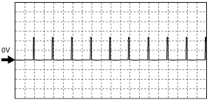
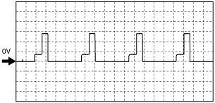
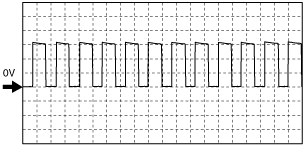
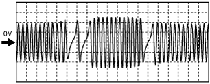
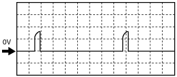
Inspection Using An Oscilloscope (Reference)
Throttle control (+)
ar8uuw00001656
|
Throttle control (–)
ar8jjw00003043
|
Purge control
ar8uuw00000182
|
APV motor control (+)
ar8jjw00003045
|
OCV control
ar8jjw00003044
|
APV motor control (–)
ar8jjw00003045
|
Eccentric shaft position sensor
ar8uuw00000184
|
Field coil control (Generator)
ar8uuw00000179
|
Generator output voltage
ar8uuw00000183
|
Ignition coil (L/F, L/R, T/F, T/R)
ar8uuw00000189
|
Fuel injector (FS, RS) control
ar8uuw00000178
|
Fuel injector (FP, RP) control
ar8uuw00000180
|
ar8uuw00000181
|
HO2S heater control
ar8uuw00002102
|
A/F sensor heater control
ar8uuw00000176
|
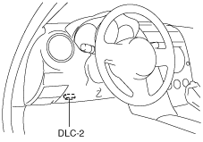
Using the M-MDS
1. Connect the M-MDS to the DLC-2.
ar8uuw00001795
|
2. Turn the ignition switch to ON position.
3. Measure the PID value.
PID/DATA monitor table (reference)
|
Monitor item (Definition) |
Unit/Condition |
Condition/Specification (Reference) |
Inspection item(s) |
PCM terminal |
|
|---|---|---|---|---|---|
|
ACCS (A/C relay)
|
Off/On
|
Idling
• A/C operating: On
• A/C not operating: Off
|
• The following PIDs
• A/C relay
|
1I
|
|
|
AC_REQ
(A/C switch)
|
Off/On
|
• A/C switch OFF: Off
• A/C switch ON: On
|
• Refrigerant pressure switch (high, low)
• A/C switch
|
1AU
|
|
|
AIP RLY (AIR pump relay)
|
Off/On
|
• During the specified period after cold: On
• Idling after warm-up: Off
|
• The following PIDs
• AIR pump relay
|
1G
|
|
|
ALTF (Generator field coil control duty value)
|
%
|
• IG SW ON: 0%
• Just after A/C switch ON and fan switch ON at idling: Duty value rises
|
• The following PIDs
• Generator
|
2AI
|
|
|
ALTT V (Generator output voltage)
|
V
|
• IG SW ON: 0 V
• Idling: Approx. 14.9 V*1 (E/L not operating)
|
Generator
|
2AJ
|
|
|
APP (APP)
|
%
|
• Accelerator pedal released: 0%
• Accelerator pedal depressed: 100%
|
• The following PIDs
• APP sensor No.1, No.2
|
1AO
1AP
|
|
|
APP1 (APP 1)
|
%
|
• Accelerator pedal released: 31.1—33.1%
• Accelerator pedal depressed: 75.6—78.6%
|
APP sensor No.1
|
1AO
|
|
|
V
|
• Accelerator pedal released: 1.555—1.655 V
• Accelerator pedal depressed: 3.78—3.93 V
|
||||
|
APP2 (APP 2)
|
%
|
• Accelerator pedal released: 20.1—22.1%
• Accelerator pedal depressed: 64.6—67.6%
|
APP sensor No.2
|
1AP
|
|
|
V
|
• Accelerator pedal released: 1.005—1.105 V
• Accelerator pedal depressed: 3.23—3.38 V
|
||||
|
APV (APV motor)
|
Open/Closed
|
• High engine speed after warm-up: Open
• Except above: Closed
|
• The following PIDs
• APV motor
|
2D
2F
|
|
|
APV_POS (APV position sensor)
|
V
|
• High engine speed after warm-up: 1.5 V or less
• Except above: 1.5 V or above
|
• APV position sensor
|
2AN
|
|
|
ARPMDES (Target engine speed)
|
RPM
|
• Indicate the target engine speed
|
• The following PIDs
|
—
|
|
|
BARO (Barometric pressure)
|
Pa, Bar, psi
|
• IG SW ON: Indicate the atmospheric pressure
|
• BARO sensor
|
—
|
|
|
V
|
• IG SW ON: 2.44—3.80 V
|
||||
|
BOO
(Brake switch (No.2 signal))
|
Off/On
|
• Brake pedal depressed: On
• Brake pedal released: Off
|
• Brake switch (No.2 signal)
|
1AB*5
|
|
|
—
|
|||||
|
CATT11_DSD
(Estimated catalytic converter temperature)
|
°C
|
°F
|
• Indicate the estimated catalytic converter temperature
|
• The following PIDs
|
—
|
|
CHRGLP (Generator warning light)
|
Off/On
|
• Generator warning light illuminate: On
• Generator warning light not illuminate: Off
|
• Generator warning light
|
—
|
|
|
COLP (Refrigerant pressure switch (middle))
|
OFF/ON
|
• Refrigerant pressure switch (middle) ON *2: ON
• Refrigerant pressure switch (middle) OFF*3: OFF
|
• Refrigerant pressure switch (middle)
|
1J
|
|
|
CPP*4
(Clutch pedal position)
|
Off/On
|
• Clutch pedal depressed: On
• Clutch pedal released: Off
|
• CPP switch
|
1D
|
|
|
CPP/PNP*4 (Shift lever position)
|
Drive/Neutral
|
• Neutral position: Neutral
• Except above: Drive
|
• Neutral switch
|
2AS
|
|
|
DEI*6 (VDI solenoid valve)
|
Off/On
|
• Idling: Off
• High engine speed after warm-up: On
|
• The following PID
• VDI solenoid valve
|
2L
|
|
|
DTCCNT (Number of DTC detected)
|
—
|
—
|
—
|
—
|
|
|
ECT (Engine coolant temperature)
|
°C
|
°F
|
• IG SW ON: Indicate the ECT
|
• ECT sensor
|
2AH
|
|
V
|
• ECT 20 °C {68 °F}: approx. 3.1 V
• ECT 80 °C {176 °F}: approx. 0.9 V
|
||||
|
EQ_RAT11
(A/F sensor)
|
—
|
• Idling after warm-up: Approx. 1
|
• A/F sensor
|
—
|
|
|
EQ_RAT11_DSD
(Target lambda)
|
—
|
• Indicate the target lambda
|
• A/F sensor
|
—
|
|
|
ETC_ACT (Electronic throttle control actual)
|
°
|
• CTP: 6.3° or less
• WOT: Approx. 83°
|
• Throttle valve actuator
|
2A
2B
|
|
|
ETC_DSD (Electronic throttle control desired)
|
°
|
• CTP: 6.3° or less
• WOT: Approx. 83°
|
• The following PIDs
|
—
|
|
|
%
|
• CTP: 7% or less
• WOT: Approx. 100%
|
||||
|
EVAPCP (Purge solenoid valve duty value)
|
%
|
• IG SW ON: 0%
• Increase the engine speed: Duty value rises
|
• The following PIDs
• Purge solenoid valve
|
2C
|
|
|
FAN1
(Cooling fan control)
|
Off/On
|
• The cooling fan is operating at low speed: On
• Except above: Off
|
• The following PIDs
• Cooling fan relay No.1
|
1M
|
|
|
FAN2
(Cooling fan control)
|
Off/On
|
• The cooling fan is operating at middle speed: On
• Except above: Off
|
• The following PIDs
• Cooling fan relay No.2, No.3
|
1N
|
|
|
FAN3
(Cooling fan control)
|
Off/On
|
• The cooling fan is operating at high speed: On
• Except above: Off
|
• The following PIDs
• Cooling fan relay No.4, No.5
|
1R
|
|
|
FLI
(Fuel level)
|
%
|
• Fuel gauge level F: Approx. 100%
• Fuel gauge level E: Approx. 0%
|
• Fuel tank gauge unit
|
—
|
|
|
FP (Fuel pump relay)
|
Off/On
|
• IG SW ON: Off
• Cranking: On
• Idling: On
|
• The following PID
• Fuel pump relay
|
1H
|
|
|
FPRR (Fuel pump speed control relay)
|
Off/On
|
• IG SW ON: Off
• Cranking: On
• Idling: Off
|
• The following PIDs
• Fuel pump speed control relay
|
1K
|
|
|
FUELPW (Fuel injector duration)
|
sec
|
• Idling after warm-up: Approx. 2.7 ms
|
• The following PIDs
• Fuel injector (FP, RP, FS, RS)
|
2AZ
2BB
2BC
2BD
|
|
|
FUELSYS
(Fuel system status)
|
OL/CL/
OL-Drive/
OL-Fault/
CL-Fault
|
• Idling after warm-up: CL
|
• The following PIDs
|
—
|
|
|
GENVDSD
(Generator voltage desired)
|
V
|
• Idling: Approx. 14.9 V*1 (E/L not operating)
|
• The following PIDs
|
—
|
|
|
HTR11
(A/F sensor heater)
|
Off/On
|
• IG SW ON: Off
• Idling after warm-up: On
|
• The following PIDs
• A/F sensor heater
|
2BG
|
|
|
HTR12
(HO2S heater)
|
Off/On
|
• IG SW ON: Off
• Idling after warm-up: On
|
• The following PIDs
• HO2S heater
|
2BE
|
|
|
IAC (Idle air control)
|
%
|
• IG SW ON: Approx. 26%
• Idling after warm-up: Approx. 21%
|
• The following PIDs
• Throttle valve actuator
|
2A
2B
|
|
|
IASV*7
(VFAD solenoid valve)
|
Off/On
|
• Idling: Off
• High engine speed: On
|
• The following PID
• VFAD solenoid valve
|
1AE
|
|
|
IAT
(Intake air temperature)
|
°C
|
°F
|
• IG SW ON: Indicate the IAT
|
• IAT sensor
|
1AT
|
|
V
|
• IAT 20 °C {68 °F}: Approx. 2.4 V
• IAT 40 °C {104 °F}: Approx. 1.5 V
|
||||
|
INGEAR (In gear)
|
Off/On
|
MT
• When the following conditions are satisfied: On
• Except above: Off
AT
• When the following conditions are satisfied: On
• Except above: Off
|
• The following PIDs
|
—
|
|
|
IVS (CTP condition)
|
Idle/
Off Idle
|
• Idling: Idle
• Except above: Off idle
|
• The following PID
|
—
|
|
|
KNOCKR (Knocking retard)
|
°
|
• IG SW ON: 0 °
• Idling: 0 °
|
• KS No.1, No.2
|
2U
2V
2Y
2AC
|
|
|
LOAD (Engine load)
|
%
|
MT
• Idling: 28.2—39.2%
• Engine speed 2,500 rpm (no load): 16.2—23.4%
AT
• Idling: 26.6—39.2%
• Engine speed 2,500 rpm (no load): 17.1—24.3%
|
• The following PIDs
|
—
|
|
|
LONGFT1 (long term fuel trim)
|
%
|
• Idling after warm-up: approx.–12.5—12.5%
|
• The following PIDs
|
—
|
|
|
MAF (Mass airflow)
|
g/sec
|
• Indicate the MAF
|
• MAF sensor
|
1AK
|
|
|
V
|
• Idling after warm-up: Approx. 1.2 V
• Engine speed 2,500 rpm (no load): Approx. 1.5 V
|
||||
|
MIL (Malfunction indicator lamp)
|
Off/On
|
• Malfunction indicator lamp illuminate : On
• Malfunction indicator lamp not illuminate: Off
|
• Instrument cluster
|
—
|
|
|
MIL_DIS (Travelled distance since the MIL illuminated)
|
Km
|
• Indicates travelled distance since the MIL illuminated
|
—
|
—
|
|
|
MOP_DRV_C (Electromagnetic metering oil pump center driving signal)
|
Off/On
|
• IG SW ON: Off
• Cranking: On
• Idling: Off
|
• Metering oil pump No.1
|
1E
|
|
|
MOP_DRV_S (Electromagnetic metering oil pump side driving signal)
|
Off/On
|
• IG SW ON: Off
• Cranking: On
• Idling: Off
|
• Metering oil pump No.2
|
1F
|
|
|
MOP_FL_C (Electromagnetic metering oil pump center request flow volume)
|
cc/h
|
• IG SW ON: 0 cc/h
• Cranking: Approx. 5 cc/h
• Idling: Approx. 1 cc/h
|
• Metering oil pump driver
|
1S
|
|
|
MOP_FL_S (Electromagnetic metering oil pump side request flow volume)
|
cc/h
|
• IG SW ON: 0 cc/h
• Cranking: Approx. 3 cc/h
• Idling: Approx. 0 cc/h
|
• Metering oil pump driver
|
1AA
|
|
|
MOP_P_ACT (Electromagnetic metering oil pump system pressure actual)
|
Pa, Bar, psi
|
• Idling: 70 KPa
|
• Oil pressure sensor
|
2R
|
|
|
MOP_P_DSD (Electromagnetic metering oil pump system pressure desired)
|
Pa, Bar, psi
|
• Indicate the target oil pressure
|
• Oil pressure sensor
|
—
|
|
|
O2S11
(A/F sensor)
|
A
|
• Idling after warm-up: Approx. 0 mA
|
• A/F sensor
|
2AD
|
|
|
O2S12
(HO2S)
|
V
|
• Idling after warm-up: 0—1.0 V
|
• HO2S
|
2Q
|
|
|
OCV_ACT (OCV current actual)
|
A
|
• IG SW ON: Approx. 300 mA
• Idling: Approx. 450 mA
|
• OCV
|
2E
|
|
|
OCV_CLEAN (OCV cleaning mode)
|
Off/On
|
• OCV cleaning mode operating: On
• Except above: Off
|
• OCV
|
2E
|
|
|
OCV_DSD (OCV current desired)
|
A
|
• Indicate the target OCV current
|
• The following PID
|
—
|
|
|
PACNTV (AIR solenoid valve control)
|
Off/On
|
• AIR pump operating: On
• AIR pump not operating: Off
|
• The following PIDs
• AIR solenoid valve
|
2G
|
|
|
PCM_T (PCM temperature sensor)
|
V
|
• IG SW ON: 1.2—2.6 V
|
• PCM temperature sensor
|
—
|
|
|
RO2FT1
(HO2S fuel trim)
|
—
|
• Idling after warm-up: approx. 0
|
• The following PID
|
—
|
|
|
RPM (Engine speed)
|
RPM
|
• Engine runs: Indicate the engine speed
|
• Eccentric shaft position sensor
|
2AG
|
|
|
SC_SET*5 (Cruise main indicator light/ cruise set indicator light)
|
Off/On
|
• Cruise main indicator light/ cruise set indicator light illuminate: On
• Cruise main indicator light/ cruise set indicator light not illuminate: Off
|
• Instrument cluster
|
—
|
|
|
SCCS*5 (Cruise control switch)
|
V
|
• ON/OFF switch pressed in: approx. 0 V
• CANCEL switch pressed in: approx. 1.1 V
• SET(-) switch pressed in: approx. 3.1 V
• RES(+) switch pressed in: approx. 4.2 V
• Except above: approx. 5.0 V
|
• Cruise control switch
|
1AQ
|
|
|
SHRTFT1
(Short term fuel trim (front))
|
%
|
• Idling after warm-up: approx.–4—4%
|
• The following PIDs
|
—
|
|
|
SHRTFT12
(Short term fuel trim (rear))
|
%
|
• Idling after warm-up: approx. 0%
|
• The following PIDs
|
—
|
|
|
SPARK-L (Ignition timing)
|
°(BTDC)
|
• Idling after warm-up: BTDC approx. –5°
|
• The following PIDs
• Ignition coil (L/F, L/R)
|
2AT
2AX
|
|
|
SPARK-T (Ignition timing)
|
°(BTDC)
|
• Idling after warm-up: BTDC approx. 10°
|
• The following PIDs
• Ignition coil (T/F, T/R)
|
2AW
2BA
|
|
|
SSV (SSV solenoid valve)
|
Off/On
|
• High engine speed after warm-up: On
• Idling: Off
|
• The following PIDs
• SSV solenoid valve
|
2I
|
|
|
Tset
|
Off/On
|
• Test mode: On
• Except above: Off
|
—
|
—
|
|
|
TIRESIZE (Tire revolution per mile)
|
rev/mile
|
• Indicates tire revolution per a mile
|
|||
|
TP (TP)
|
V
|
• CTP: Approx. 0.8 V
• WOT: Approx. 3.92 V
|
• The following PIDs
|
—
|
|
|
TP_REL (Relative TP)
|
%
|
• CTP: Approx. 7%
• WOT: Approx. 100%
|
• The following PIDs
|
2AK
2AL
|
|
|
TP1 (TP 1)
|
%
|
• CTP: 8.0—16.0%
• WOT: 76.5—81.9%
|
• TP sensor No.1
|
2AK
|
|
|
V
|
• CTP: 0.4—0.8 V
• WOT: 3.825—4.095 V
|
||||
|
TP2 (TP 2)
|
%
|
• CTP: 23.6—35.6%
• WOT: 80.66—86.06%
|
• TP sensor No.2
|
2AL
|
|
|
V
|
• CTP: 1.18—1.78 V
• WOT: 4.033—4.303 V
|
||||
|
TPCT
(TP sensor voltage at CTP)
|
V
|
• IG SW ON (CTP): Approx. 0.6 V
|
• TP sensor
|
—
|
|
|
VPWR (Battery voltage)
|
V
|
• Indicate the battery voltage
|
• Battery
|
1BA
|
|
|
VSS (Vehicle speed)
|
KPH
|
MPH
|
• Vehicle running: Indicate the vehicle speed
|
• DSC HU/CM
|
—
|