Note
• Rotate and adjust the tie rod. The difference between right and left dimension L shown in the figure should be within the specification.
ar8uuw00000258
|
FRONT WHEEL ALIGNMENT
id021100800200
Specification (Unloaded Condition)
Front wheel alignment [Standard suspension]
|
Item |
Specification |
||
|---|---|---|---|
|
Total toe-in
|
Tire [Tolerance ±4 mm {0.15 in}]
|
(mm {in})
|
2 {0.08}
|
|
|
degree
|
0°11′±22′
|
|
|
Steering angle [Tolerance ±3°]
|
Inner
|
38°36′
|
|
|
Outer
|
33°18′
|
||
|
Steering axis inclination (Reference value)
|
10°56′
|
||
|
Camber
[Tolerance ±1°]
|
Vehicle height: From the end of the front fender to the center of the wheel (mm {in})
|
365—374 {14.4—14.7}
|
-0°37′
|
|
375—384 {14.8—15.1}
|
-0°17′
|
||
|
385—394 {15.2—15.5}
|
0°01′
|
||
|
395—404 {15.6—15.9}
|
0°17′
|
||
|
405—414 {16.0—16.2}
|
0°31′
|
||
|
Caster
[Tolerance ±1°]
|
Vehicle height: From the end of the rear fender to the center of the wheel (mm {in})
|
375—384 {14.8—15.1}
|
6°33′
|
|
385—394 {15.2—15.5}
|
6°21′
|
||
|
395—404 {15.6—15.9}
|
6°08′
|
||
|
405—414 {16.0—16.2}
|
5°55′
|
||
|
415—424 {16.4—16.6}
|
5°43′
|
||
Front wheel alignment [Sports suspension]
|
Item |
Specification |
||
|---|---|---|---|
|
Total toe-in
|
Tire [Tolerance ±4 mm {0.15 in}]
|
(mm {in})
|
2 {0.08}
|
|
|
degree
|
0°11′±22′
|
|
|
Steering angle [Tolerance ±3°]
|
Inner
|
38°36′
|
|
|
Outer
|
33°18′
|
||
|
Steering axis inclination (Reference value)
|
10°59′
|
||
|
Camber
[Tolerance ±1°]
|
Vehicle height: From the end of the front fender to the center of the wheel (mm {in})
|
363—372 {14.3—14.6}
|
-0°41′
|
|
373—382 {14.7—15.0}
|
-0°21′
|
||
|
383—392 {15.1—15.4}
|
-0°03′
|
||
|
393—402 {15.5—15.8}
|
0°14′
|
||
|
403—412 {15.9—16.2}
|
0°28′
|
||
|
Caster
[Tolerance ±1°]
|
Vehicle height: From the end of the rear fender to the center of the wheel (mm {in})
|
366—375 {14.5—14.7}
|
6°45′
|
|
376—385 {14.9—15.1}
|
6°33′
|
||
|
386—395 {15.2—15.5}
|
6°20′
|
||
|
396—405 {15.6—15.9}
|
6°07′
|
||
|
406—415 {16.0—16.3}
|
5°55′
|
||
Front wheel alignment [Sports suspension equipped with Bilstein]
|
Item |
Specification |
||
|---|---|---|---|
|
Total toe-in
|
Tire [Tolerance ±4 mm {0.15 in}]
|
(mm {in})
|
2 {0.08}
|
|
|
degree
|
0°11′±22′
|
|
|
Steering angle [Tolerance ±3°]
|
Inner
|
38°36′
|
|
|
Outer
|
33°18′
|
||
|
Steering axis inclination (Reference value)
|
11°12′
|
||
|
Camber
[Tolerance ±1°]
|
Vehicle height: From the end of the front fender to the center of the wheel (mm {in})
|
356—365 {14.1—14.3}
|
-0°57′
|
|
366—375 {14.5—14.7}
|
-0°35′
|
||
|
376—385 {14.9—15.1}
|
-0°15′
|
||
|
386—395 {15.2—15.5}
|
0°02′
|
||
|
396—405 {15.6—15.9}
|
0°18′
|
||
|
Caster
[Tolerance ±1°]
|
Vehicle height: From the end of the rear fender to the center of the wheel (mm {in})
|
364—373 {14.4—14.6}
|
6°47′
|
|
374—383 {14.8—15.0}
|
6°35′
|
||
|
384—393 {15.2—15.4}
|
6°22′
|
||
|
394—403 {15.6—15.8}
|
6°09′
|
||
|
404—413 {16.0—16.2}
|
5°57′
|
||
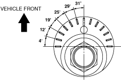
Steering Angle Adjustment
1. Loosen the locknut of the tie-rod end.
2. Remove the rack boot clamp.
3. Rotate the tie rod and adjust the steering angle.
ar8uuw00000258
|
4. Tighten the locknut of the tie-rod end.
5. Correct the rack boot deformation.
6. Install and fix the rack boot clamp.
7. After adjusting the steering angle, always inspect and adjust the toe angle. (See Total Toe-in Adjustment.)
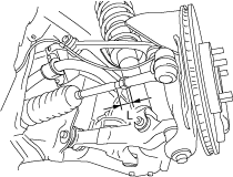
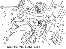
Camber Adjustment
1. Loosen the fixing nut of the adjusting cam bolt (front lower arm front side).
chu0211w006
|
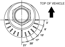
2. Rotate the adjusting cam bolt in either direction to adjust the camber.
e5u211zw5001
|
Standard suspension
|
Vehicle height* |
Camber |
|---|---|
|
365—374 {14.4—14.7}
|
-0°37′
|
|
375—384 {14.8—15.1}
|
-0°17′
|
|
385—394 {15.2—15.5}
|
0°01′
|
|
395—404 {15.6—15.9}
|
0°17′
|
|
405—414 {16.0—16.2}
|
0°31′
|
Sports suspension
|
Vehicle height* |
Camber |
|---|---|
|
363—372 {14.3—14.6}
|
-0°41′
|
|
373—382 {14.7—15.0}
|
-0°21′
|
|
383—392 {15.1—15.4}
|
-0°03′
|
|
393—402 {15.5—15.8}
|
0°14′
|
|
403—412 {15.9—16.2}
|
0°28′
|
Sports suspension equipped with Bilstein
|
Vehicle height* |
Camber |
|---|---|
|
356—365 {14.1—14.3}
|
-0°57′
|
|
366—375 {14.5—14.7}
|
-0°35′
|
|
376—385 {14.9—15.1}
|
-0°15′
|
|
386—395 {15.2—15.5}
|
0°02′
|
|
396—405 {15.6—15.9}
|
0°18′
|
|
|
Left wheel |
Right wheel |
|---|---|---|
|
Positive direction
|
Clockwise
|
Counterclockwise
|
|
Negative direction
|
Counterclockwise
|
Clockwise
|
ar8wzw00001098
|
3. Tighten the nut.
4. Adjust the toe-in.
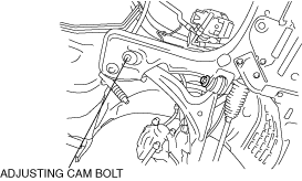
Caster Adjustment
1. Loosen the installation nut of the adjusting cam bolt (front lower arm rear side).
chu0211w027
|
2. Rotate the adjusting cam bolt in either direction to adjust the caster.
chu0211w022
|
Standard suspension
|
Vehicle height* |
Caster |
|---|---|
|
375—384 {14.8—15.1}
|
6°33′
|
|
385—394 {15.2—15.5}
|
6°21′
|
|
395—404 {15.6—15.9}
|
6°08′
|
|
405—414 {16.0—16.2}
|
5°55′
|
|
415—424 {16.4—16.6}
|
5°43′
|
Sports suspension
|
Vehicle height* |
Caster |
|---|---|
|
366—375 {14.5—14.7}
|
6°45′
|
|
376—385 {14.9—15.1}
|
6°33′
|
|
386—395 {15.2—15.5}
|
6°20′
|
|
396—405 {15.6—15.9}
|
6°07′
|
|
406—415 {16.0—16.3}
|
5°55′
|
Sports suspension equipped with Bilstein
|
Vehicle height* |
Caster |
|---|---|
|
364—373 {14.4—14.6}
|
6°47′
|
|
374—383 {14.8—15.0}
|
6°35′
|
|
384—393 {15.2—15.4}
|
6°22′
|
|
394—403 {15.6—15.8}
|
6°09′
|
|
404—413 {16.0—16.2}
|
5°57′
|
|
|
Left wheel |
Right wheel |
|---|---|---|
|
Increase
|
Counterclockwise
|
Clockwise
|
|
Decrease
|
Clockwise
|
Counterclockwise
|
ar8wzw00001099
|
3. Tighten the nut.
4. Adjust the camber and total toe-in.
Total Toe-in Adjustment
1. Loosen the locknut of the tie-rod end.
2. Remove the rack boot clamp.
3. Adjust the total toe-in by rotating each tie rod (left and right) in the opposite directions by the same amount respectively.
4. Tighten the locknut of the tie-rod end.
5. Verify that the rack boot does not have any twisting, and install the rack boot clamp.