 |
ar8wzw00000280
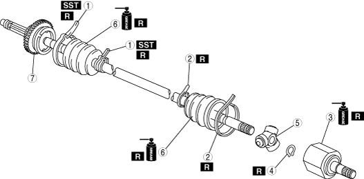
REAR DRIVE SHAFT DISASSEMBLY/ASSEMBLY
id031300800700
1. Disassemble in the order indicated in the table.
2. Assemble in the reverse order of disassembly.
ar8wzw00000280
|
|
1
|
Boot band (axle side)
|
|
2
|
Boot band (differential side)
|
|
3
|
Outer ring
(See Outer Ring Disassembly Note.)
(See Outer Ring Assembly Note.)
|
|
4
|
Snap ring
|
|
5
|
Tripod joint
|
|
6
|
Boot
(See Boot Disassembly Note.)
(See Boot Assembly Note.)
|
|
7
|
Shaft and ball joint component
|
Boot Band (axle side) Disassembly Note
1. Remove the boot band using end clamp pliers.
ar8wzw00000281
|
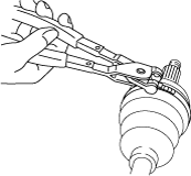
Boot Band (Differential Side) Disassembly Note
1. Remove the crimp of the clip using a flathead screwdriver.
ar8wzw00000282
|
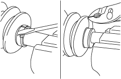
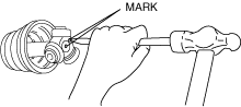
Outer Ring Disassembly Note
1. Place an alignment mark on the drive shaft and the outer ring.
chu0313w005
|
2. Remove the outer ring.
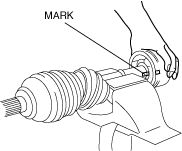
Snap Ring, Tripod Joint Disassembly Note
1. Place an alignment mark on the shaft and tripod joint.
2. Remove the snap ring using a snap ring plier.
chu0313w006
|
3. Remove the tripod joint from the shaft.
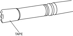
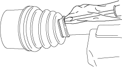
Boot Disassembly Note
1. Wrap the shaft spline with vinyl tape.
chu0313w007
|
2. Remove the boot.
Boot Assembly Note
1. Fill the inside of the new dust boot (wheel side) with grease.
2. Install the boot with the drive shaft spline still wrapped with vinyl tape.
3. Remove the vinyl tape.
Tripod Joint, Snap Ring Assembly Note
1. Align the tripod joint with the shaft mark and insert it using a brass bar.
chu0313w008
|
2. Install the new snap ring to the shaft installation slot securely using a snap ring pliers.
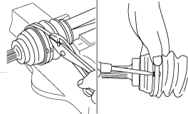
Outer Ring Assembly Note
1. Fill the outer ring and boot (differential side) with the repair kit grease.
2. Assemble the outer ring.
3. Release any trapped air from the boots by carefully lifting up the small end of each boot with a cloth wrapped screwdriver.
ar8wzw00000283
|
4. Set the drive shaft length to the specification when the inside of the boots is at ambient pressure.
Rear drive shaft standard length (mm {in})
|
MT
|
Left side
|
792.6—802.6 {31.21—31.59}
|
|
Right side
|
832.6—842.6 {32.78—33.17}
|
|
|
AT
|
Left side
|
791.1—801.1 {31.15—31.53}
|
|
Right side
|
831.1—841.1 {32.71—33.11}
|
5. After installation, verify that there is no boot damage or grease leakage.
Boot Band (Differential Side) Assembly Note
1. Using pliers, pull the boot band around the boot slot in opposite direction of drive shaft forward rotation direction and tighten.
ar8wzw00000284
|
2. Insert the end of the boot band between the boot band clip and fold back the clip tabs using a flathead screwdriver to secure the boot band.
3. Verify that the boot band is installed to the boot slot securely.
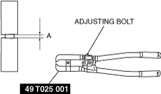
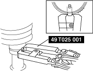
Boot Band (Axle Side) Assembly Note
Boot band (small diameter side)
1. Adjust clearance A by turning the adjusting bolt of the SST.
chu0313w009
|
2. Crimp the wheel side small boot band using the SST. Verify that clearance B is within the specification.
ar8wzw00000285
|
3. Verify that the boot band does not protrude from the boot band installation area.
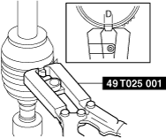
Boot band (Large diameter side)
1. Adjust clearance C by turning the adjusting bolt of the SST.
chu0313w009
|
2. Crimp the wheel side large boot band using the SST. Verify that clearance D is within the specification.
ar8uuw00002521
|
3. Verify that the boot band does not protrude from the boot band installation area.