|
ar8wzw00000314
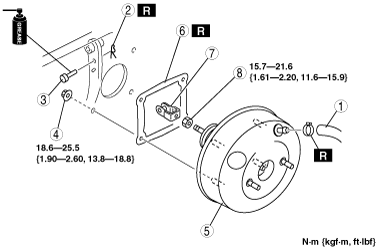
POWER BRAKE UNIT REMOVAL/INSTALLATION
id041100801800
1. Remove the engine cover. (See ENGINE COVER REMOVAL/INSTALLATION [13B-MSP].)
2. Remove the front suspension tower bar. (MT) (See FRONT SUSPENSION TOWER BAR REMOVAL/INSTALLATION [MT].)
3. Remove the air pump. (R.H.D.) (See SECONDARY AIR INJECTION (AIR) PUMP REMOVAL/INSTALLATION [13B-MSP].)
4. Remove the master cylinder. (See MASTER CYLINDER REMOVAL/INSTALLATION.)
5. Remove in the order indicated in the table.
6. Remove the brake switch. (See BRAKE PEDAL REMOVAL/INSTALLATION.)
7. Install in the reverse order of removal.
8. After installation, perform brake pedal inspection. (See BRAKE PEDAL INSPECTION.)
L.H.D.
ar8wzw00000314
|
|
1
|
Brake pipe
|
|
2
|
Vacuum hose
|
|
3
|
Snap pin
|
|
4
|
Clevis pin
|
|
5
|
Nut
|
|
6
|
Power brake unit
|
|
7
|
Gasket
|
|
8
|
Fork
|
|
9
|
Locknut
|
R.H.D.
ar8wzw00000315
|
|
1
|
Vacuum hose
|
|
2
|
Snap pin
|
|
3
|
Clevis pin
|
|
4
|
Nut
|
|
5
|
Power brake unit
|
|
6
|
Gasket
|
|
7
|
Fork
|
|
8
|
Locknut
|