 |
e5u513zw5032
SOLENOID VALVE INSPECTION [SJ6A-EL]
id051311253200
Resistance inspection (On-vehicle)
1. Remove the engine cover. (See ENGINE COVER REMOVAL/INSTALLATION [13B-MSP].)
2. Remove the battery cover.
3. Disconnect the negative battery cable.
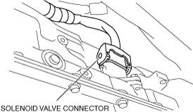
4. Disconnect the solenoid valve connector.
e5u513zw5032
|
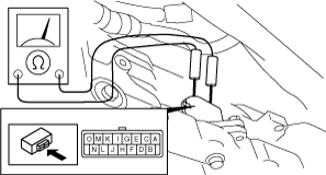
5. Measure the resistance between the following terminals.
ar8wzw00000157
|
Solenoid valve resistance (ATF temperature: 20 °C {68 °F})
|
Terminals |
Solenoid valve |
Resistance (ohm) |
|---|---|---|
|
O—GND
|
Shift solenoid A
|
11—15
|
|
N—GND
|
Shift solenoid B
|
11—15
|
|
M—GND
|
Shift solenoid C
|
11—15
|
|
L—GND
|
Shift solenoid D
|
11—15
|
|
K—GND
|
Shift solenoid E
|
11—15
|
|
E—F
|
Shift solenoid F
|
5.0—5.6
|
|
C—D
|
Shift solenoid G
|
5.0—5.6
|
|
I—J
|
Line pressure control solenoid
|
5.0—5.6
|
|
G—H
|
TCC control solenoid
|
5.0—5.6
|
6. Connect the solenoid valve connector.
7. Connect the negative battery cable.
8. Install the battery cover.
9. Install the engine cover. (See ENGINE COVER REMOVAL/INSTALLATION [13B-MSP].)
Continuity Inspection (On-Vehicle Inspection)
1. Remove the engine cover. (See ENGINE COVER REMOVAL/INSTALLATION [13B-MSP].)
2. Remove the battery cover.
3. Disconnect the negative battery cable.
4. Disconnect the solenoid valve connector.
e5u513zw5032
|
5. Verify that there is no continuity between coupler component terminals C, D, E, F, G, H, I, J and GND.
6. Connect the solenoid valve connector.
7. Connect the negative battery cable.
8. Install the battery cover.
9. Install the engine cover. (See ENGINE COVER REMOVAL/INSTALLATION [13B-MSP].)