 |
ar8uuw00001014
STEERING GEAR AND LINKAGE DISASSEMBLY/ASSEMBLY
id061300282300
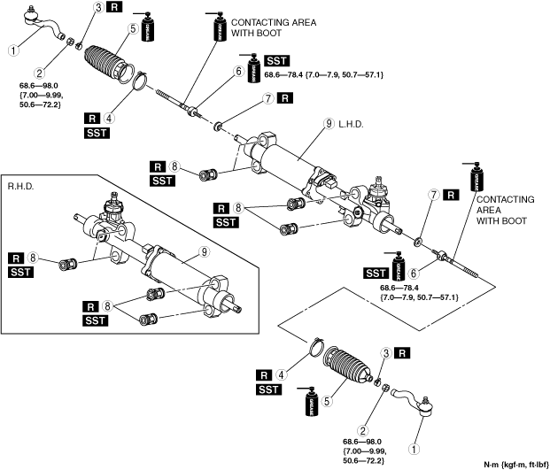
1. Disassemble in the order indicated in the table.
2. Assemble in the reverse order of disassembly.
ar8uuw00001014
|
|
1
|
Tie-rod end
(See Tie-rod End Disassembly Note.)
|
|
2
|
Locknut
|
|
3
|
Boot clamp
|
|
4
|
Boot band
(See Boot Band Assembly Note.)
|
|
5
|
Boot
|
|
6
|
Tie rod
(See Tie Rod Disassembly Note.)
(See Tie Rod Assembly Note.)
|
|
7
|
Lock washer
|
|
8
|
Mounting rubber
|
|
9
|
Steering gear and linkage
|
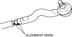
Tie-rod End Disassembly Note
1. Place alignment marks as shown in the figure for proper installation.
ar8uuw00001015
|
2. Remove the tie-rod end.
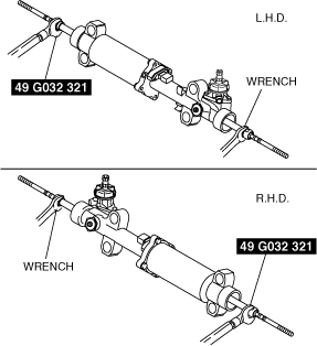
Tie Rod Disassembly Note
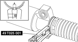
1. Lock the steering rack end (pinion gear side) against rotation with a wrench.
ar8wzw00000237
|
2. Using the SST, remove the tie rod.
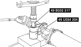
Mounting Rubber Disassembly Note
1. Press the mounting rubber out from the gear housing using the SSTs and a press.
ar8uuw00001017
|
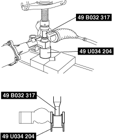
Mounting Rubber Assembly Note
1. Apply soapy water to the rubber part of the mounting rubber.
2. Press the mounting rubber until the mounting rubber end comes out completely from the gear housing using the SSTs and a press.
ar8uuw00001018
|
3. Reverse the gear housing, then press the mounting rubber until the mounting rubber end comes out completely from the other side. At this time, verify that the mounting rubber and steel pipe are aligned.
ar8uuw00001019
|
Tie Rod Assembly Note
1. Lock the steering rack end (pinion gear side) against rotation with a wrench.
ar8wzw00000237
|
2. Using the SST, tighten the tie rod.
Boot Band Assembly Note
1. Crimp the boot band using the SST.
ar8uuw00001020
|
2. Verify that the crimping clearance A is within the specification.
3. Rotate the boot by hand and verify that it is securely installed to the boot band.