|
ar8wzw00000442
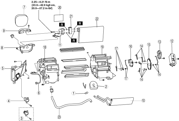
A/C UNIT DISASSEMBLY/ASSEMBLY
id071100800300
1. Disassemble in the order indicated in the table.
2. Assemble in the reverse order of disassembly.
L.H.D.
ar8wzw00000442
|
R.H.D.
ar8wzw00000443
|
|
1
|
Drain hose
|
|
2
|
Polyurethane foam (1)
|
|
3
|
Power transistor (Full-auto air conditioner)
|
|
4
|
Resistor (Manual air conditioner)
|
|
5
|
Air duct
|
|
6
|
Evaporator temperature sensor
|
|
7
|
Polyurethane foam (2)
|
|
8
|
Bracket (1)
|
|
9
|
Bracket (2)
|
|
10
|
Heater core
|
|
11
|
Evaporator pipe
|
|
12
|
A/C amplifier
|
|
13
|
Airflow mode actuator
|
|
14
|
Airflow mode link set
|
|
15
|
Airflow mode main link
|
|
16
|
Air mix actuator
|
|
17
|
Air mix link set
|
|
18
|
A/C case (1)
|
|
19
|
A/C case (2)
|
|
20
|
Adhesive polyurethane
|
|
21
|
Expansion valve
|
|
22
|
Evaporator
|
|
23
|
Air hose
|
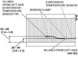
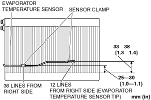
Evaporator Temperature Sensor Disassembly Note
1. Mark the installation positions (2 locations) for the sensor clamps used to install the evaporator temperature sensor to the evaporator, and the position for the tip of the evaporator temperature sensor.
2. Remove the evaporator temperature sensor.
Evaporator Temperature Sensor Assembly Note
When evaporator is replaced
1. Assemble the evaporator temperature sensor as shown in the figure.
L.H.D.
ar8uuw00002207
|
R.H.D.
ar8wzw00000845
|
When evaporator is not replaced
1. Install the evaporator temperature sensor by aligning it with the positions marked prior to removal.