AIRFLOW VOLUME CONTROL OPERATION [FULL-AUTO AIR CONDITIONER]
id0740a1102600
Order of Priority for Controls
1. Blower motor correction at start
2. Airflow volume manual control
3. MAX HOT and MAX COLD correction
4. Airflow volume automatic control
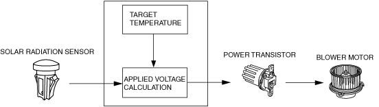
Airflow Volume Automatic Control
• The A/C amplifier calculates the applied voltage to the blower motor based on the input from the solar radiation sensor and the target temperature, and outputs the drive signal to the power transistor. However, the warm-up correction and the mild start correction take precedence under the operation conditions of the warm-up correction and the mild start correction.
• Applied voltage to the blower motor is as follows.
|
Air volume level
|
Blower motor applied voltage (V)
|
|
1
|
3.4
|
|
2
|
3.7
|
|
3
|
4.1
|
|
4
|
4.4
|
|
5
|
4.7
|
|
6
|
5.0
|
|
7
|
5.3
|
|
8
|
5.7
|
|
9
|
6.0
|
|
10
|
6.3
|
|
11
|
6.6
|
|
12
|
7.0
|
|
13
|
7.3
|
|
14
|
7.6
|
|
15
|
7.9
|
|
16
|
8.2
|
|
17
|
8.5
|
|
18
|
8.9
|
|
19
|
9.2
|
|
20
|
9.5
|
|
21
|
9.8
|
|
22
|
10.1
|
|
23
|
10.5
|
|
24
|
10.8
|
|
25
|
11.1
|
|
26
|
11.4
|
|
27
|
11.7
|
|
28
|
12.1
|
|
29
|
12.4
|
|
30
|
12.7
|
|
31 (MAX HI)
|
B+
|
Correction
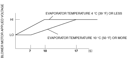
Mild start correction
• Controls blower motor applied voltage for a maximum of 17 s when the blower motor is started in summer to prevent discomfort caused by a high volume of hot air blown from the blow-off opening. However, the mild start correction is not performed when the airflow is in a mode other than VENT, the A/C mode is off, or the target temperature is high.
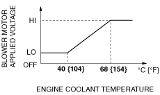
Warm-up correction
• Controls blower motor applied voltage in accordance with the increase in engine coolant temperature to prevent discomfort caused by a high volume of cold air blown from the blow-off opening. However, the warm-up correction is not performed in a mode other than HEAT or HEAT/DEF, or when the target temperature is low.
MAX HOT and MAX COLD correction
• If the set temperature is at MAX HOT*1, or MAX COLD*2, the blower motor applied voltage is fixed at HI. However, during the warm-up correction, the MAX HOT correction is not performed.
*1 : 29.0 (European (L.H.D. U.K.) specs.), 32.0 (Australian specs.)
*2 : 15.0 (European (L.H.D. U.K.) specs.), 18.0 (Australian specs.)
Defroster correction
• When the defroster switch is turned on, air volume is increased by adding blower motor applied voltage (2 V) to improve defrosting.
Burn prevention function at start
• If the blower motor is started from a stopped condition with a blower motor applied voltage at 4.0 V or more, the blower motor applied voltage is fixed at 4.0 V for 2 s to prevent blower motor burning due to excess electrical current.
Airflow Volume Manual Control
• The blower motor applied voltage (air volume) can be switched between seven steps by operation of the fan switch.
|
Fan switch
|
Blower motor applied voltage
|
|
1st speed
|
3.4 V
|
|
2nd speed
|
5.0 V
|
|
3rd speed
|
6.6 V
|
|
4th speed
|
8.2 V
|
|
5th speed
|
9.8 V
|
|
6th speed
|
11.4 V
|
|
7th speed
|
B+
|