 |
ar8wzw00001173
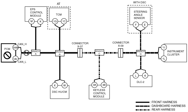
DETERMINING MALFUNCTIONING PART (HS-CAN) [MULTIPLEX COMMUNICATION SYSTEM (L.H.D.)]
id0902j3846700
1. Verify the CAN system-related module DTCs and the failed module on the M-MDS screen.
2. Refer to “DTC Output Pattern and Malfunctioning Part” and find the area linked from the malfunctioning part.
3. Inspect the possible cause and inspection item of the applicable malfunctioning part.
4. Perform the DTC inspection after the repair procedure.
DTC Output Pattern and Malfunctioning Part
|
M-MDS display |
DTC output pattern and malfunctioning part |
||||||||||
|---|---|---|---|---|---|---|---|---|---|---|---|
|
DTC output module |
DTC |
||||||||||
|
PCM
(PCM)
|
U0101
|
|
|
|
×
|
|
|
|
|
|
|
|
U0121
|
|
|
|
|
×
|
|
|
|
|
|
|
|
U0155
|
|
|
|
|
|
|
|
|
|
×
|
|
|
U0167
|
|
|
|
|
|
|
×
|
|
|
|
|
|
EPS
(EPS control module)
|
U01900
|
×
|
|
|
|
|
|
|
|
|
|
|
U2023
|
-
|
|
|
|
×
|
|
|
|
|
|
|
|
TCM*1
(TCM)
|
U0100
|
×
|
|
×
|
|
|
|
|
|
|
|
|
U0121
|
|
|
|
|
×
|
|
|
|
|
|
|
|
ABS
(DSC HU/CM)
|
U0100
|
×
|
|
×
|
|
|
|
|
|
|
|
|
U0101
|
|
|
|
×
|
|
|
|
|
|
|
|
|
U0155
|
|
|
|
|
|
|
|
|
|
×
|
|
|
U1900
|
-
|
|
-
|
|
|
|
|
|
|
|
|
|
U2023
|
-
|
|
-
|
|
|
|
|
|
|
|
|
|
RKE
(Keyless control module)
|
U1147
|
×
|
|
×
|
|
|
×
|
|
|
|
|
|
U2510
|
-
|
|
-
|
|
|
-
|
|
|
|
|
|
|
SASM
(Steering angle sensor)
|
U1900
|
|
|
|
|
×
|
×
|
|
×
|
|
|
|
IC
(Instrument cluster)
|
U1900
|
×
|
×
|
×
|
×
|
×
|
×
|
×
|
×
|
|
|
|
U2023
|
-
|
|
|
|
×
|
×
|
|
×
|
|
|
|
|
M-MDS display module
|
“Fail” display pattern
|
||||||||||
|
PCM
|
×
|
|
×
|
|
|
×
|
|
×
|
|
|
|
|
EPS
|
|
×
|
×
|
|
|
×
|
|
×
|
|
|
|
|
TCM*1
|
|
|
|
×
|
|
×
|
|
×
|
|
|
|
|
ABS
|
|
|
|
|
×
|
×
|
|
×
|
|
|
|
|
RKE
|
|
|
|
|
|
|
×
|
×
|
|
|
|
|
SASM
|
|
|
|
|
|
|
|
|
×
|
|
|
|
IC
|
|
|
|
|
|
|
|
|
|
×
|
|
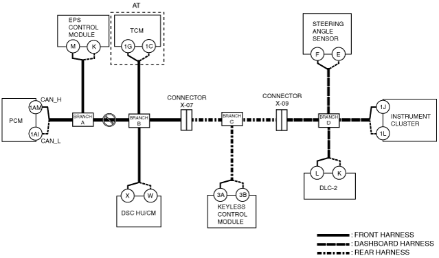
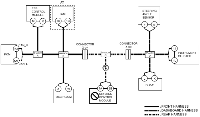
A
Possible cause
System wiring diagram
ar8wzw00001173
|
Inspection item
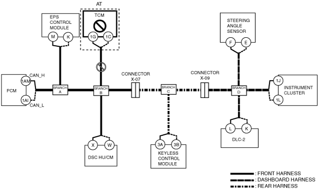
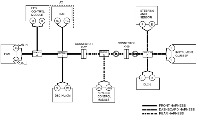
B
Possible cause
System wiring diagram
ar8wzw00001174
|
Inspection item
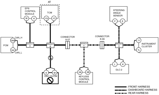
C
Possible cause
System wiring diagram
ar8wzw00001175
|
Inspection item
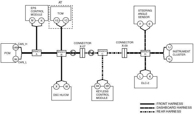
D
Possible cause
System wiring diagram
ar8wzw00001176
|
Inspection item
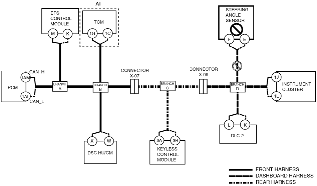
E
Possible cause
System wiring diagram
ar8wzw00001182
|
Inspection item
F
Possible cause
System wiring diagram
ar8wzw00001177
|
Inspection item
G
Possible cause
System wiring diagram
ar8wzw00001178
|
Inspection item
H
Possible cause
System wiring diagram
ar8wzw00001179
|
Inspection item
I
Possible cause
System wiring diagram
ar8wzw00001180
|
Inspection item
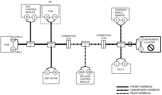
J
Possible cause
System wiring diagram
ar8wzw00001181
|
Inspection item