 |
ar8uuw00002564
POWER WINDOW SUBSWITCH INSPECTION
id091200802200
Vehicles With Exterior Open/close Function
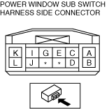
1. Measure the voltage at each terminal is as indicated in the Terminal Voltage Tables.
Terminal Voltage Table(Reference)
ar8uuw00002564
|
|
Terminal |
Signal name |
Connected to |
Measured condition |
Voltage (V)/Continuity |
Inspection item (s) |
|---|---|---|---|---|---|
|
A
|
Open output
|
Power window motor
|
While door glass is opening
|
1.0 or less
|
Power window motor
|
|
While door glass is closing
|
B+
|
||||
|
B
|
GND
|
Body ground
|
Under any condition
|
1.0 or less
|
GND
|
|
C
|
Serial
|
Power window main switch
|
• Because this terminal is for communication, good/no good judgment by terminal voltage is not possible.
• Inspect the wiring harness between power window subswitch terminal C and power window main switch terminal H for the following:
|
Power window main switch
|
|
|
D
|
GND
|
Power window motor
|
Under any condition:Inspect for continuity to ground
|
Continuity detected
|
Power window motor
|
|
E
|
Pulse 1
|
Power window motor
|
Door glass moving
|
Approx. 6
|
Power window motor
|
|
Door glass stopped
|
0 or B+
|
||||
|
G
|
Pulse 2
|
Power window motor
|
Door glass moving
|
Approx. 6
|
Power window motor
|
|
Door glass stopped
|
0 or B+
|
||||
|
I
|
Power supply
|
Power window motor
|
Ignition switch at ON
|
B+
|
Power window motor
|
|
J
|
Power cut
|
Power window main switch
|
• Ignition switch at ON
• Power cut switch at off
|
0.25
|
• Related wiring harness
• Power window subswitch
|
|
Ignition switch at ACC or LOCK
|
1.0 or less
|
||||
|
Power cut switch at on
|
1.0 or less
|
||||
|
K
|
Close output
|
Power window motor
|
Door glass moving
|
Approx. 6
|
Power window motor
|
|
Door glass stopped
|
1.0 or les
|
||||
|
L
|
Power supply
|
P.IWND1 30 A fuse
|
Under any condition
|
B+
|
P.IWND1 30 A fuse
|
1. Turn the ignition switch to ON position, and verify the LED illuminates.
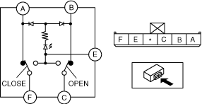
Vehicles Without Exterior Open/close Function
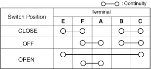
1. Verify continuity as indicated in the table.
ar8wzw00001137
|
ar8wzw00001138
|
2. Connect battery positive voltage to terminal E and ground to the terminal A. Verify that continuity exists.
3. Connect battery positive voltage to terminal E and ground to the terminal B. Verify that continuity exists.