 |
ar8wzw00001032
FRONT SEAT BACK TRIM REMOVAL/INSTALLATION
id091300912000
L.H.D.
Removal
1. Turn the ignition switch to LOCK position.
2. Disconnect the negative battery cable and wait 1 min or more.
3. Remove the front seat. (See FRONT SEAT REMOVAL/INSTALLATION.)
4. Remove the Walk-in switch. (Vehicles with power seat) (See WALK-IN SWITCH REMOVAL/INSTALLATION.)
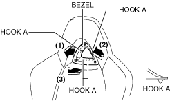
5. Pull the bezel in the order of (1),(2),(3) shown in the figure to remove the hooks A.
ar8wzw00001032
|
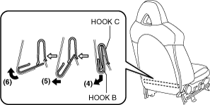
6. Remove the bezel.
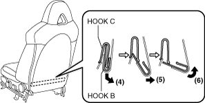
7. Slide hook B in the order of (4), (5), (6) shown in the figure to detach it from hook C.
ar8wzw00001033
|
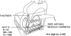
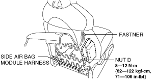
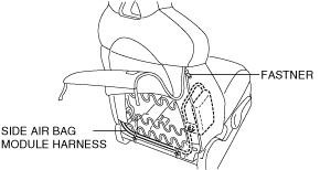
8. Open the fastener.
ar8uuw00002008
|
9. Remove the nut D.
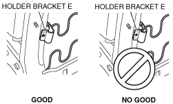
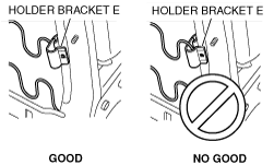
10. Press in the holder bracket E to the seat back pad being careful not to catch the frame spring.
ar8wzw00001034
|
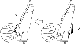
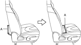
11. Pull out part A shown in the figure to the front.
ar8wzw00001035
|
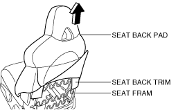
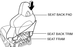
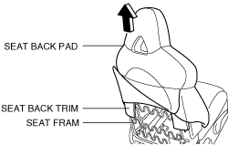
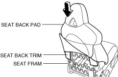
12. Remove the seat back trim and the seat back pad as a single unit from the seat frame by pulling them in the direction of the arrow.
ar8wzw00001036
|
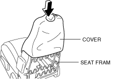
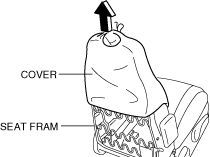
13. Remove the cover.
ar8wzw00001037
|
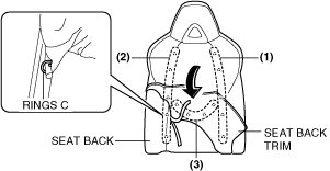
14. Partially peal back the seat back trim from the seat back pad, remove rings C in the order of (7), (8), (9) shown in the figure, then remove the seat back trim.
ar8wzw00001038
|
Installation
1. Install the seat back trim to the front seat back pad, install the rings C in the order of (1), (2), (3) shown in the figure, then install the seat back trim.
ar8wzw00001039
|
2. Install the cover.
ar8wzw00001040
|
3. Install the seat back trim and the seat back pad as a single unit from the seat frame by pushing them in the direction of the arrow
ar8wzw00001041
|
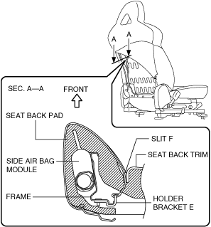
4. Pass holder bracket E through slit F of the seat back pad.
ar8wzw00001042
|
ar8wzw00001043
|
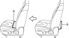
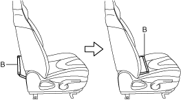
5. Push the part B shown in the figure to the rear.
ar8uuw00002019
|
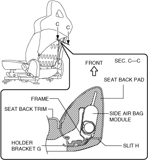
6. Pass holder bracket G through slit H of the seat back pad.
ar8wzw00001044
|
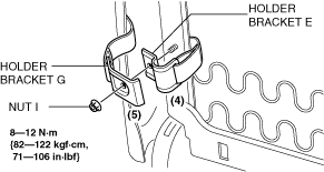
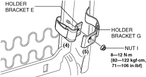
7. Assemble the holder bracket E, G to the frame in the order of (4), (5) shown in the figure.
ar8wzw00001045
|
8. Install the nut I.
9. shut the fastener.
ar8uuw00002022
|
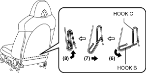
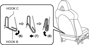
10. Slide hook B in the order of (6), (7), (8) shown in the figure to install it to hook C
ar8wzw00001046
|
11. Push the bezel and install the hooks A.
ar8wzw00001047
|
12. Install the bezel.
R.H.D.
Removal
1. Turn the ignition switch to LOCK position.
2. Disconnect the negative battery cable and wait 1 min or more.
3. Remove the front seat. (See FRONT SEAT REMOVAL/INSTALLATION.)
4. Remove the Walk-in switch. (Vehicles with power seat) (See WALK-IN SWITCH REMOVAL/INSTALLATION.)
5. Pull the bezel in the order of (1),(2),(3) shown in the figure to remove the hooks A.
ar8wzw00001032
|
6. Remove the bezel.
7. Slide hook B in the order of (4), (5), (6) shown in the figure to detach it from hook C.
ar8wzw00001048
|
8. Open the fastener.
ar8wzw00001049
|
9. Remove the nut D.
10. Press in the holder bracket E to the seat back pad being careful not to catch the frame spring.
ar8wzw00001050
|
11. Pull out part A shown in the figure to the front.
ar8wzw00001051
|
12. Remove the seat back trim and the seat back pad as a single unit from the seat frame by pulling them in the direction of the arrow.
ar8wzw00001052
|
13. Remove the cover.
ar8wzw00001053
|
14. Partially peal back the seat back trim from the seat back pad, remove rings C in the order of (7), (8), (9) shown in the figure, then remove the seat back trim.
ar8wzw00001038
|
Installation
1. Install the seat back trim to the front seat back pad, install the rings C in the order of (1), (2), (3) shown in the figure, then install the seat back trim.
ar8wzw00001039
|
2. Install the cover.
ar8wzw00001054
|
3. Install the seat back trim and the seat back pad as a single unit from the seat frame by pushing them in the direction of the arrow
ar8wzw00001055
|
4. Pass holder bracket E through slit F of the seat back pad.
ar8wzw00001056
|
ar8wzw00001057
|
5. Push the part B shown in the figure to the rear.
ar8wzw00001058
|
6. Pass holder bracket G through slit H of the seat back pad.
ar8wzw00001059
|
7. Assemble the holder bracket E, G to the frame in the order of (4), (5) shown in the figure.
ar8wzw00001060
|
8. Install the nut I.
9. shut the fastener.
ar8wzw00001061
|
10. Slide hook B in the order of (6), (7), (8) shown in the figure to install it to hook C
ar8wzw00001062
|
11. Push the bezel and install the hooks A.
ar8wzw00001047
|
12. Install the bezel.